How alternator works diy voltage regulator. Connect a length of 10 gauge wire to the output stud on the back of the alternator using a solderless ring connector.
Mercury Grand Marquis Questions Alternator Wiring Problems
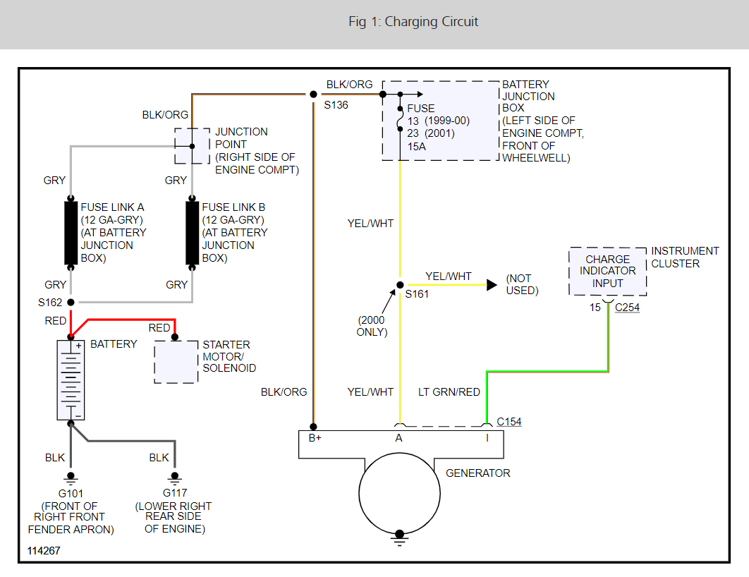
Alternator wiring diagram. It was also used in a lot of off road equipment so theyre generally cheap and easy to find. A wiring diagram is a simplified traditional pictorial depiction of an electrical circuit. It is a diagram for the alternator in a ford focus see also ford focus repair manual ford escort ford f 100 ford taurus ford mustang ford model t ford gt40 ford thunderbird ford shelby cobra and other ford cars that use the similar alternator. This rotor spins past wire coils causing a magnetic field. Collection of delco 3 wire alternator wiring diagram. Ford alternator wiring diagram.
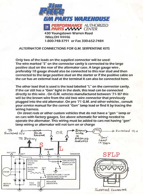
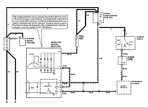
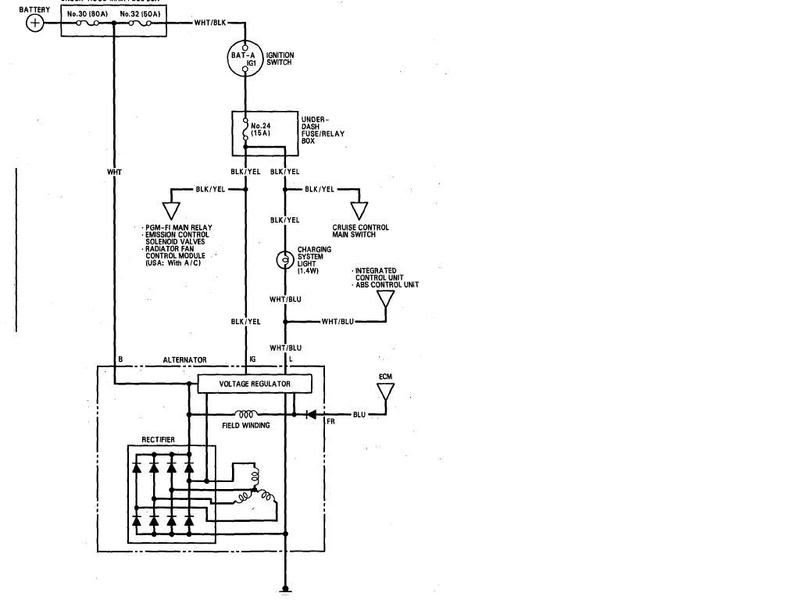
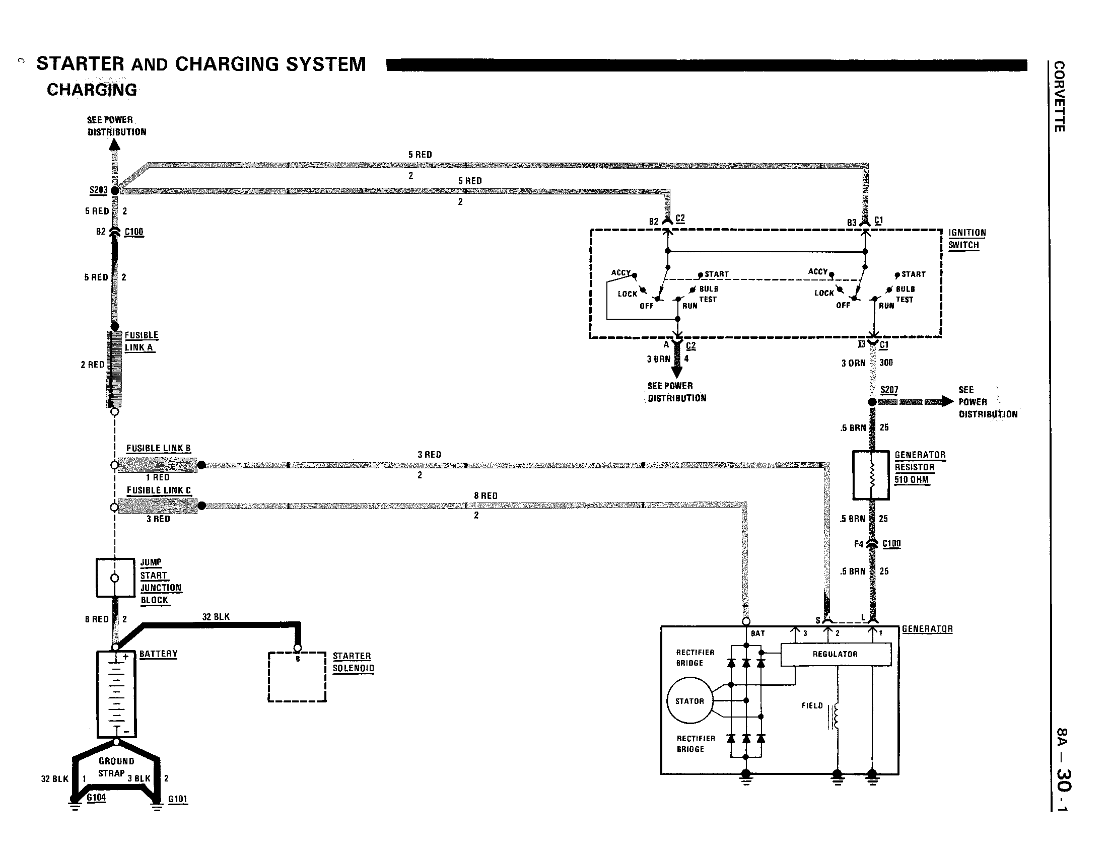
This diagram shows how to wire a delco gm internally regulated 3 wire alternator. The resistor or directly to the key switch itself switched side. This wiring configuration will excite the alternator to start charging when the engine is running at low rpms. If you are able to look at a manufacturers diagram of the alternators connectors the wire that slides over pin 1 of the alternator leads to the positive connection on the vehicles battery and senses voltage. Figure 1 below is a block diagram or a functional diagram of an alternator and its connections to the remainder of the automobile electrical system. Wiring this alternator is well within the capabilities of anyone with average mechanical skills.
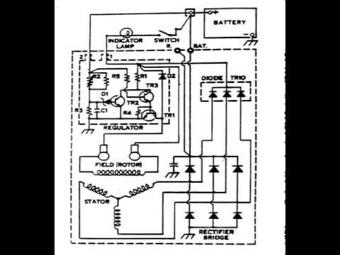
If the voltage rises above or falls below 12 volts the alternators internal voltage increases or reduces power output to. A wiring diagram usually gives details regarding the loved one placement as well as plan of tools as well as terminals on the tools to assist in structure or servicing the device. Charge wire connects from the alternator to the battery through the. A wiring diagram is a simplified conventional photographic depiction of an electric circuit. Collection of denso alternator wiring schematic. This particular model 10si used in the 1970s and early 80s is the one youll find on the generation of gm cars most often used in demolition derbies.
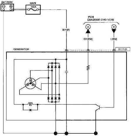
Disconnect the battery negative terminal. This is the diagram of every components in the alternator. Connect the opposite end of this wire to the starter solenoid. The other terminal is the exciter. It reveals the elements of the circuit as simplified forms and the power and also signal connections in between the tools. It reveals the elements of the circuit as streamlined shapes and the power and signal links in between the gadgets.
Gallery of Alternator Wiring Diagram