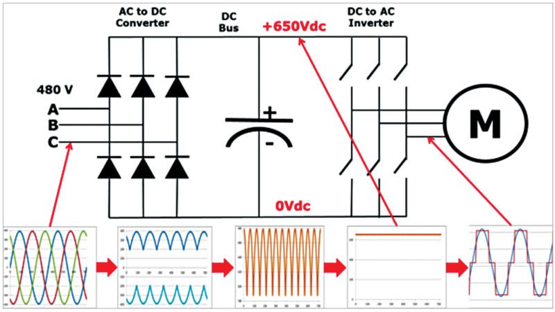
Standard industrial drives both ac and dc use six rectifier devices to form a three phase full wave bridge. Vfd pwm waveform the diagram below shows a common waveform for a pulse width modulation pwm circuit in the vfd.
Vfd Fundamentals
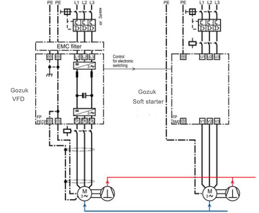
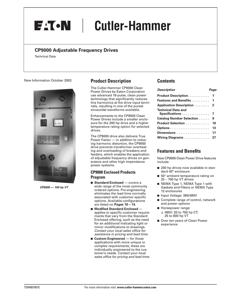
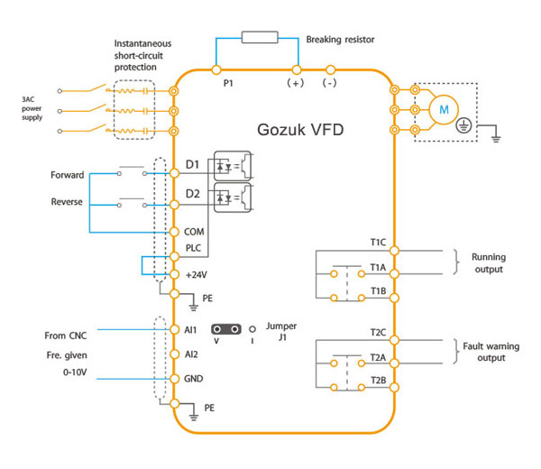
18 pulse vfd wiring diagram. Demand more clean power. They prevent upstream transformer overheating and overloading enabling the application of generators and other high impedance systems. How to wire circuit protection breaker and fuse. Make sure to connect the ground terminal to an appropriate safety ground. Learn the basic wiring of variable frequency drives vfd with our electrician steve quist. The drive has terminals available to connect a dc link choke.
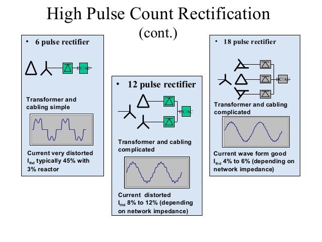
Published on oct 18 2018. Wire and cable wiring and grounding guidelines for pulse width modulated pwm ac drives installation instructions publication drives in001 see chapter1 input power cables on page22. To comply with regulations different solutions should be considered. The vfds showed in the video are the d720s 230v single phase and the d720 230v three phase. It shows the parts of the circuit as streamlined forms and the power and also signal links between the gadgets. A typical diagram of a series connected eighteen pulse drive constructed from a standard six pulse drive two external rectifiers and a conventional 18 pulse isolation transformer appears in figure 1.
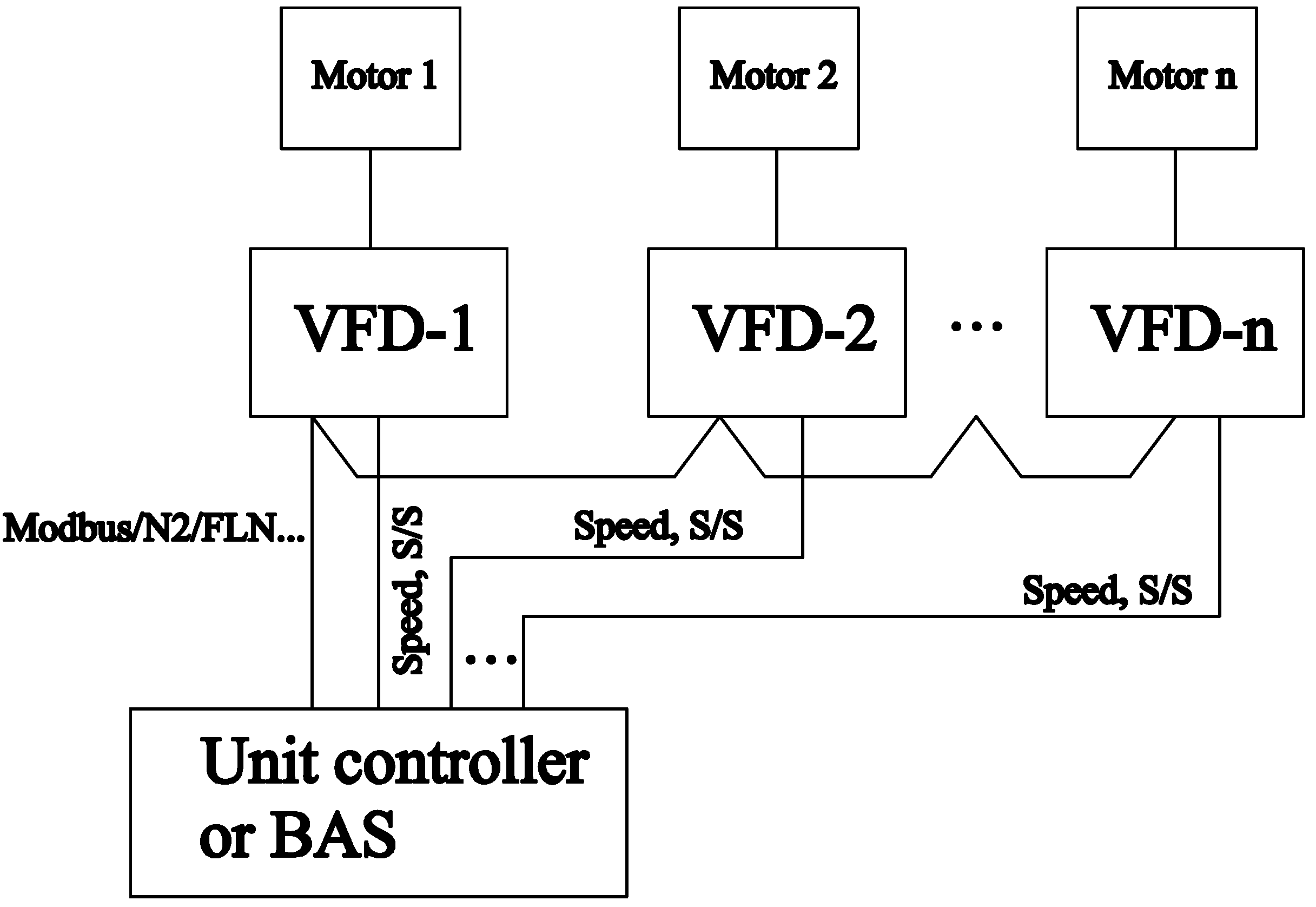
Similarly 18 pulse vfd be could be triple in size and cost compared to a 6 pulse vfd. The cpx series of variable frequency drives uses advanced 18 pulse clean power technology that significantly reduces line harmonics at the drive input terminalsresulting in one of the purest sinusoidal waveforms available. Multi pulse vfds 18 pulse phase shifting isolation transformer provides dual outputs that go to 3 separate rectifiers. 6 pulse vfd built in dc line reactor 6 pulse vfd built in dc line reactor external harmonic filter higher pulse vfd 0 1 9 10 8 7 6 5 4 3 2 6 pulse vfd. These terminals are used. We strongly recommend using a certified electrician to set up your vfds.
This type of converter is called a six pulse design because it draws current in six distinct pulses from the ac line. In this video we used the very popular mitsubishi d700 series vfd showing single phase and three phase wiring instructions. Emc filters powerflex 750 series products with totalforce control installation instructions publication 750 in100 see chapter 3 installation. This isnt useful in a dc drive but works fine for ac variable frequency drive vfd. Starting a vfd with 2 wire start duration. A wiring diagram is a simplified standard photographic depiction of an electric circuit.
18 diodes turns 3 phase power into 9 phase power 18 pulse input current 18 pulse utility input voltage. Assortment of vfd wiring diagram. Main circuit wiring variable frequency drive wire input to terminals l1 l2 and l3 for three phase input. Advantages guarantees compliance with.
Gallery of 18 Pulse Vfd Wiring Diagram