The tip of the rocket igniter consists of a very thin wire bridge wire coated with a chemical compound that heats up pyrogenpyrotechnic. If its too violent the run goes up in tire smoke.
A Begineer S Guide To Diy Model Rocket
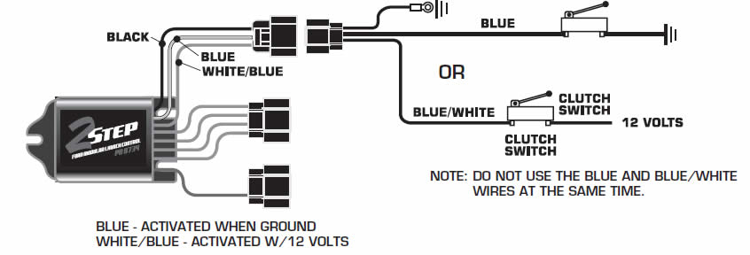
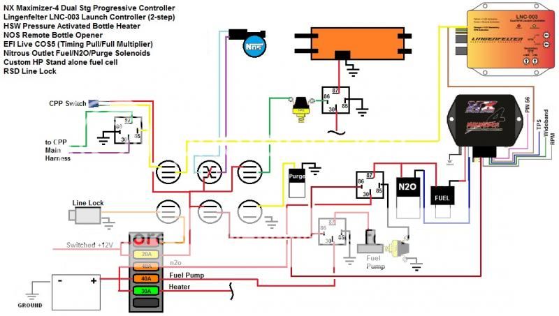
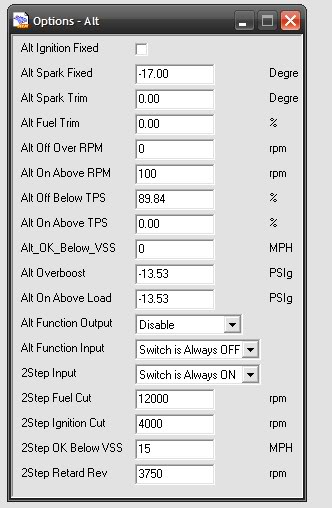
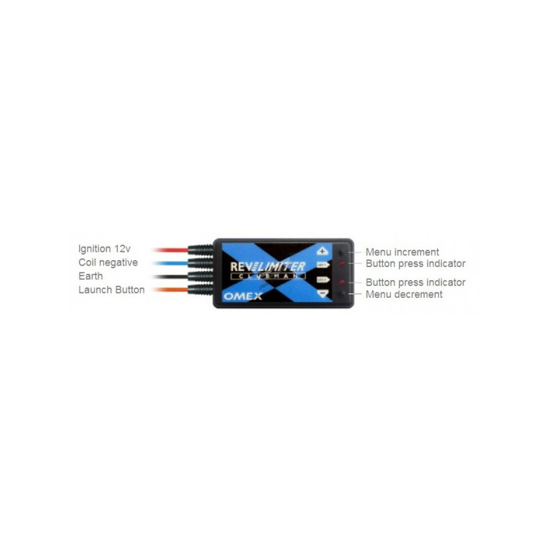
Launch control wiring diagram. Until now taming a nitrous system. Too soft and et. Having recently purchased a starter kit for an alpha iii model rocket i was unfortunately underwhelmed with the controller supplied in the kit. Model rocket ignition controller. Launch control may be run with either the factory clutch switch or an external switch. Select power commander tools configure feature enables and selection inputs.
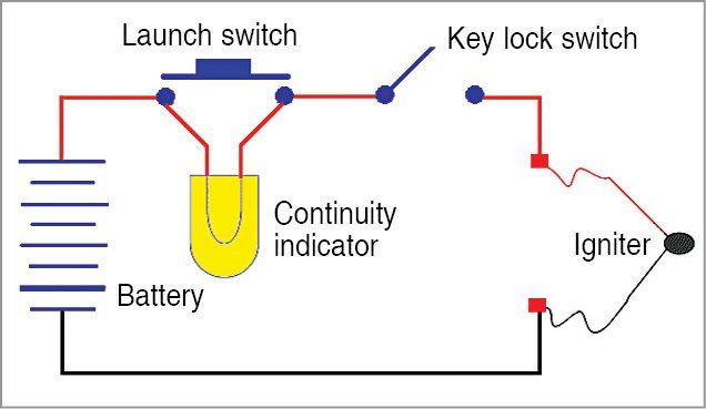
Launch control will be active when the switch is closed. How to make a simple rocket launcher controller for model rocketry. Article includes photos of launches and rocket parachute descent. An external switch is required to activate launch control. As well as details on improvements incorporated in a more complex controller. Includes a schematic of a simple two switch controller circuit as well as recommendations to purchase switches with a high enough current rating.
Is left on the table. Mark the location of the mounting holes then drill the holes using an 18 bit. The main issue for me being the standard 9volt battery not producing enough power to the igniter to eff. Also make sure the wiring reaches the msd ignition. It is recommended to mount the launch control within easy reach of the driver so last minute adjustments can be made to the launch rpm setting. When enabled launch control will hold the bike at the chosen rpm regardless of the throttle position.
Since making runs on the knife edge of traction is essential to get the win light serious nitrous racers utilize methods to soften the hit when they squeeze the juice. Any racer will tell you its easy to make horsepowergetting it to ground is the hard part. Use the supplied mounting screws to secure the control. If you are using an external switch for launch control connect the pin labeled launch control input connector to a switch and connect the other side of the switch to a chassis ground. To configure launch control for your power commander v fuel tuner please follow the instructions below. If you do not plan to use the transbrake bump.
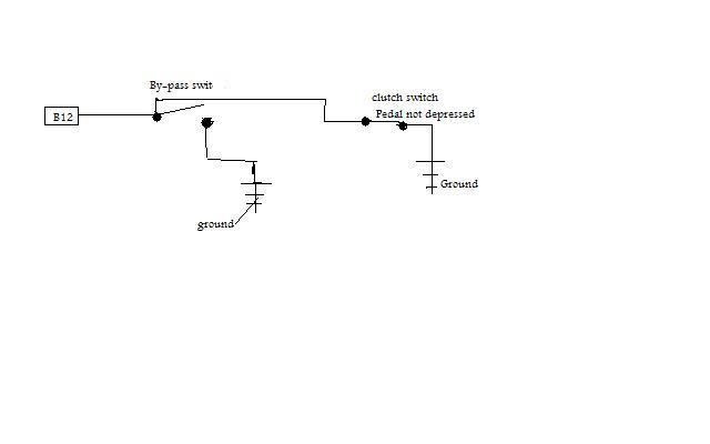
Model rocket launch controller generic wiring diagram in principle a model rocket igniter is no different than any other piece of wire. Typically a little more fuel would be added in order to assist with in cylinder temperatures but the ignition timing is a little more tricky. The launch control function also allows us to make fueling and ignition changes while the function is active. Wiring diagrams for launch control activation with transbrake button in general transbrake buttons cannot be connected directly to the inputs on the cortex ebc unless the transbrake bump feature is being utilized in conjunction with a solenoidpump driver. In regards to the above diagram im interested to know the reason for the second diode. Launch control wiring schematics v22 by symtech laboratories thu sep 20 2012 424 pm crazy2287 wrote.
