If not the structure wont function as it ought to be. A wiring diagram is a streamlined traditional photographic depiction of an electric circuit.

Fit A Japanese Regulator Rectifier Unit To A 12v Ac Dc Royal
Yamaha outboard rectifier wiring diagram. Ask the experts on our yamaha outboard forum for repair issues diagnosing problems links to diagrams suggestions on buying parts and more. Here is a listing of common color codes for yamaha outboard motors. There is an industry standard set of wire codes in general use by most manufacturers except yamaha. A first check out a circuit layout may be complicated however if you can check out a metro map you could check out schematics. Yamaha outboard wiring diagram pdf a beginner s overview of circuit diagrams. Yamaha outboard ignition switch wiring diagram yamaha 115 outboard ignition switch wiring diagram yamaha outboard ignition switch wiring diagram yamaha outboard key switch wiring diagram every electrical structure consists of various unique components.
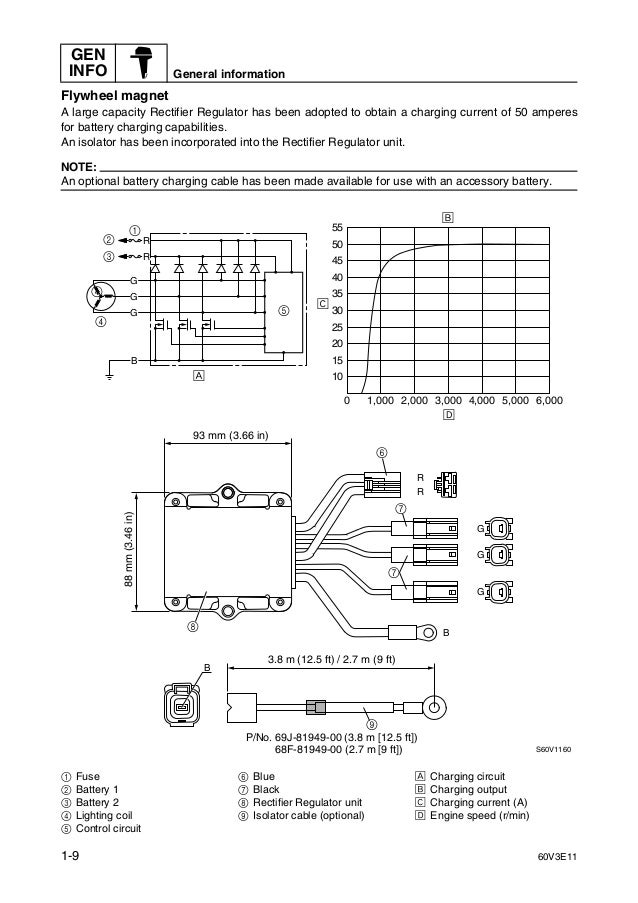
A wiring diagram usually gives details regarding the loved one position as well as plan of gadgets and terminals on the tools to help in building or servicing the tool. From looking at the wiring diagrams it appears the downward facing green wire exiting the rr in the bottom right corner is the tach signal wire to the 703 remote. Collection of yamaha outboard wiring diagram pdf. It shows the parts of the circuit as streamlined shapes as well as the power and also signal connections in between the tools. Colors listed here may vary with year model but in general should be a good guide when tracing yamaha wiring troubles. Ive ordered a rectifier based.
F70 yamaha trim gauge wiring trusted wiring diagram online yamaha outboard gauges wiring diagram yamaha 2000 r1 5jj wiring diagram yamaha fz6n wiring diagram yamaha ytm200el wiring diagram. Each part should be set and linked to other parts in particular way.


