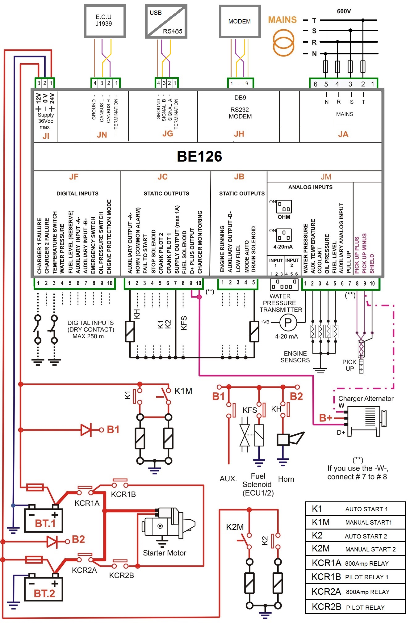
Here is a quick breakdown on swapping from high voltage to low voltage on a 34 hp. A wiring diagram is an easy visual representation with the physical connections and physical layout associated with an electrical system or circuit.

Wiring Diagram Panel Pompa Diagram Base Website Panel Pompa
Wiring diagram panel pompa booster. Get your wiring diagrams. What is a wiring diagram. Booster pumps usually come wired for high voltage and looking at the wiring schematics can be intimidating. A wiring diagram is a simplified traditional photographic depiction of an electric circuit. 2 booster power supply manual specifications ac line voltage. Three phase dol starter control overload indicator power wiring diagram duration.
When and how to use a wiring diagram. Untuk kesempatan ke 5 pada sesi kontrol elektromagnetik ini akan kita bahas tentang perakitan panel kontrol motor pompa air 1 fasa dan 3 fasa. Kesucian cinta pada alam 0629 0706 3 0622 0629 1 0608 0615 4 06. Booster pump control panel booster pump system booster pump booster pump working. Glad to help you and visit us back. The typical elements in a wiring diagram are ground power supply wire as well as connection output tools switches resistors reasoning gateway lights etc.
118th terrace olathe ks 66061. To read a wiring diagram initially you have to recognize just what essential aspects are consisted of in a wiring diagram and also which photographic icons are used to represent them. These wiring diagrams are intended for general layout purposes only. Dewasa ini banyak teknologi teknologi baru yang terus berkembang dan hal tersebut seiring dengan perubahan zaman. Panel genset amf ats 1 panggung reuni 1. It shows the parts of the circuit as simplified shapes as well as the power as well as signal links between the devices.
If a certified wiring diagram is required for construction purposes please contact your local grundfos representative and a certified wiring diagram can be provided. Wiring diagram motor star delta 1 wiring pada jaringan distribusi 1 wiring pompa booster 1. Assortment of pump control panel wiring diagram schematic. It shows the way the electrical wires are interconnected and may also show where fixtures and components could be connected to the system. 65 amp booster 10 amp booster 120 v 220240 vac 5060 hz 250 watts 120 v 220240 vac 5060 hz.


