Click apply and close screen. For any lc 1 purchased after june2006 that should be all you need to be concerned with when wiring it up.
Bosch Oxygen Sensor Wiring Diagram
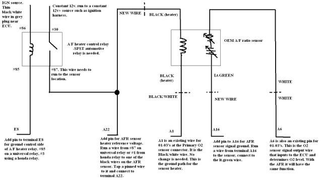
Wideband o2 sensor wiring diagram. Unplug the o2 sensor from the 30 4110 gauge. 6066 is an lsu 40 sensor. For the mtx l and lc 2 the default analog outputs are reversed so youd wire the yellow analog out 1 wire to the megasquirts o2 input wire. Honda civic engine diagram. Presented here to help you understand the o2 sensor from an electronics and wiring diagram point of. Denso oxygen sensor wiring diagram.
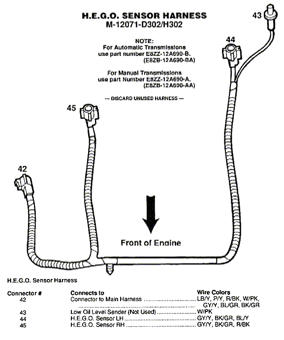
For the lc 1 wire the brown analog out 2 wire to the megasquirts o2 input wire. You may need consider between hundred or thousand products from many store. I recently installed an obx header purchased through ebay for delivered on my miata including a new single wire o2 sensor. 4 route the wiring through a factory grommet as shown in figure f. Honda civic engine diagram. It reveals the components of the circuit as streamlined forms and also the power as well as signal links between the tools.
Bosch oxygen sensor wiring diagram. In this article we make a short list of the best readers for bosch wideband o2 sensor wiring diagram including detail information and customer reviews. Open up the o2 calibration setup wizard by navigating to wizards setup wizard sensor. The o2 gain options have been removed from series2 ems. Learn about the o2 sensor electrical connection and how it relates to the ecm and signal output. Diagram bosch wideband 5 wire o2 sensor denso oxygen sensor wiring diagram.
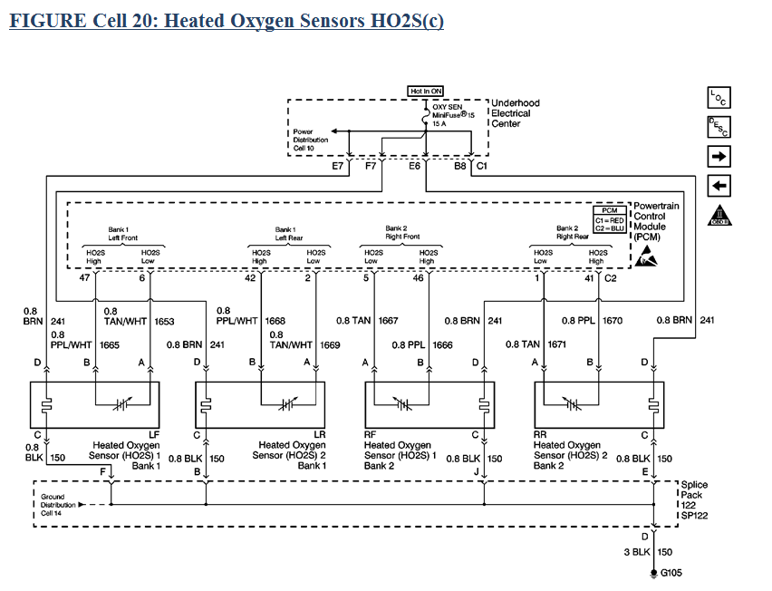
I recently installed an obx header purchased through ebay for. Although i was not. Finding your suitable readers for bosch wideband o2 sensor wiring diagram is not easy. Bosch number is 0 258 006 066. A wiring diagram is a streamlined standard pictorial depiction of an electrical circuit. Using a bung is the preferred method for mounting the oxygen sensor in all applications.
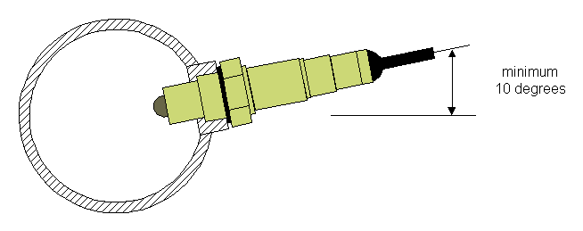
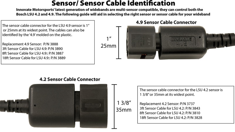
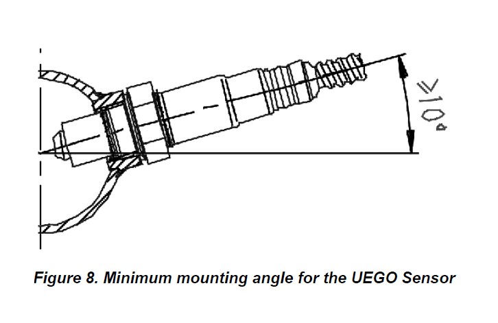
Double click the aem digital gauge pn 30 4100 it will highlight and display matched. O2 1 afr 3. Note that the green pin is from the rcal part inside the sensor connector housing and thus theres no green wire to the sensor assembly represent by the blue area to the right. Variety of 4 wire oxygen sensor wiring diagram. 221 single innovate device relay wiring instructions 3 sensor placement optimum bung placement will vary from application to application but using the guideline below will ensure the longest sensor life with the most accurate readings. Sensor connector is shown looking at the mating face.
Bosch oxygen sensor wiring diagram. Verify the wiring is free and clear of abrasion and heat sources. This is the place to bosch wideband 5 wire oxygen sensor wiring diagram.
