Variety of vfd motor wiring diagram. Collection of abb vfd wiring diagram.
Controlling 3 Phase Induction Motor Using Vfd And Plc
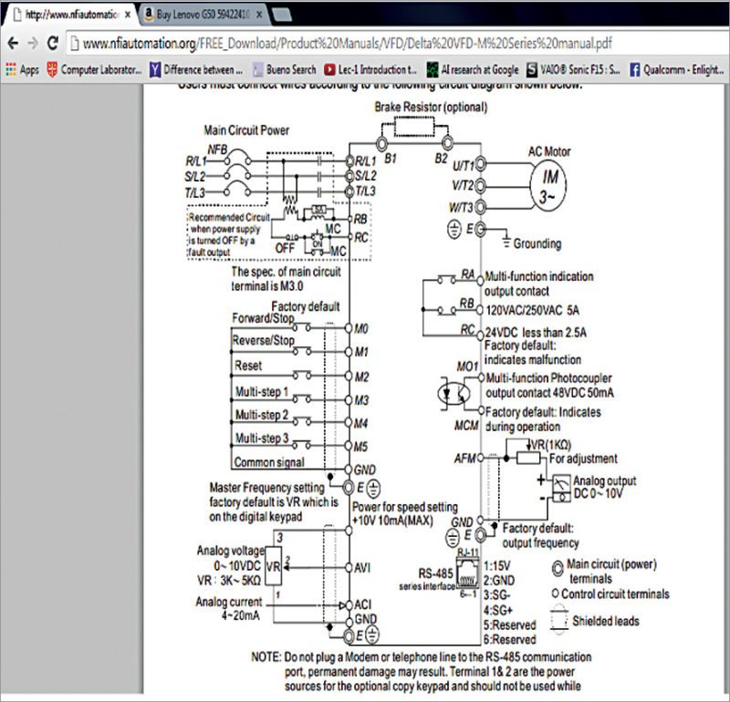
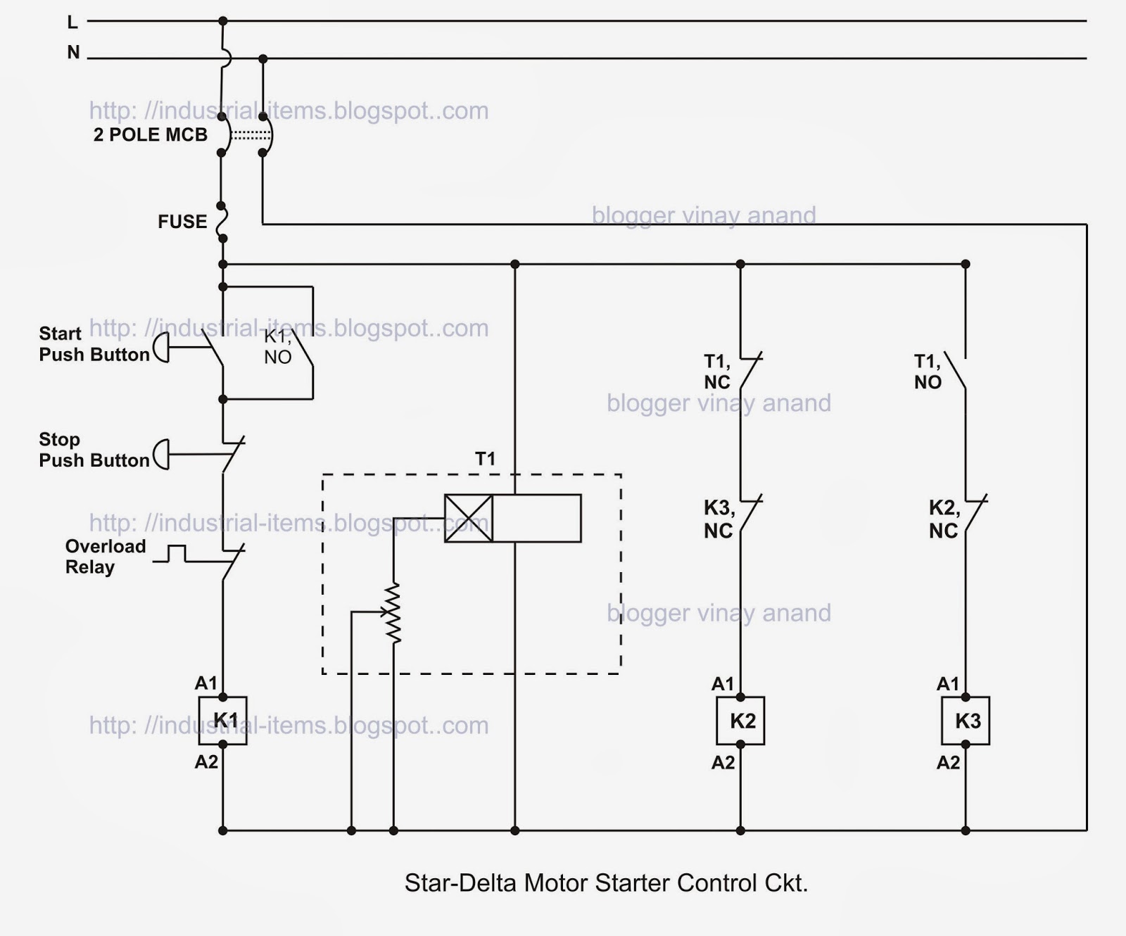
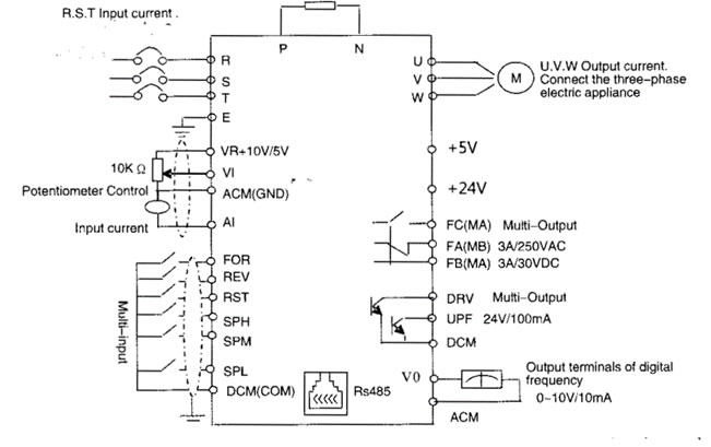
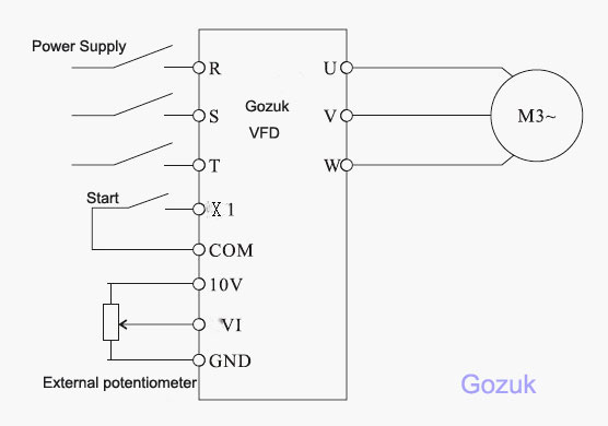
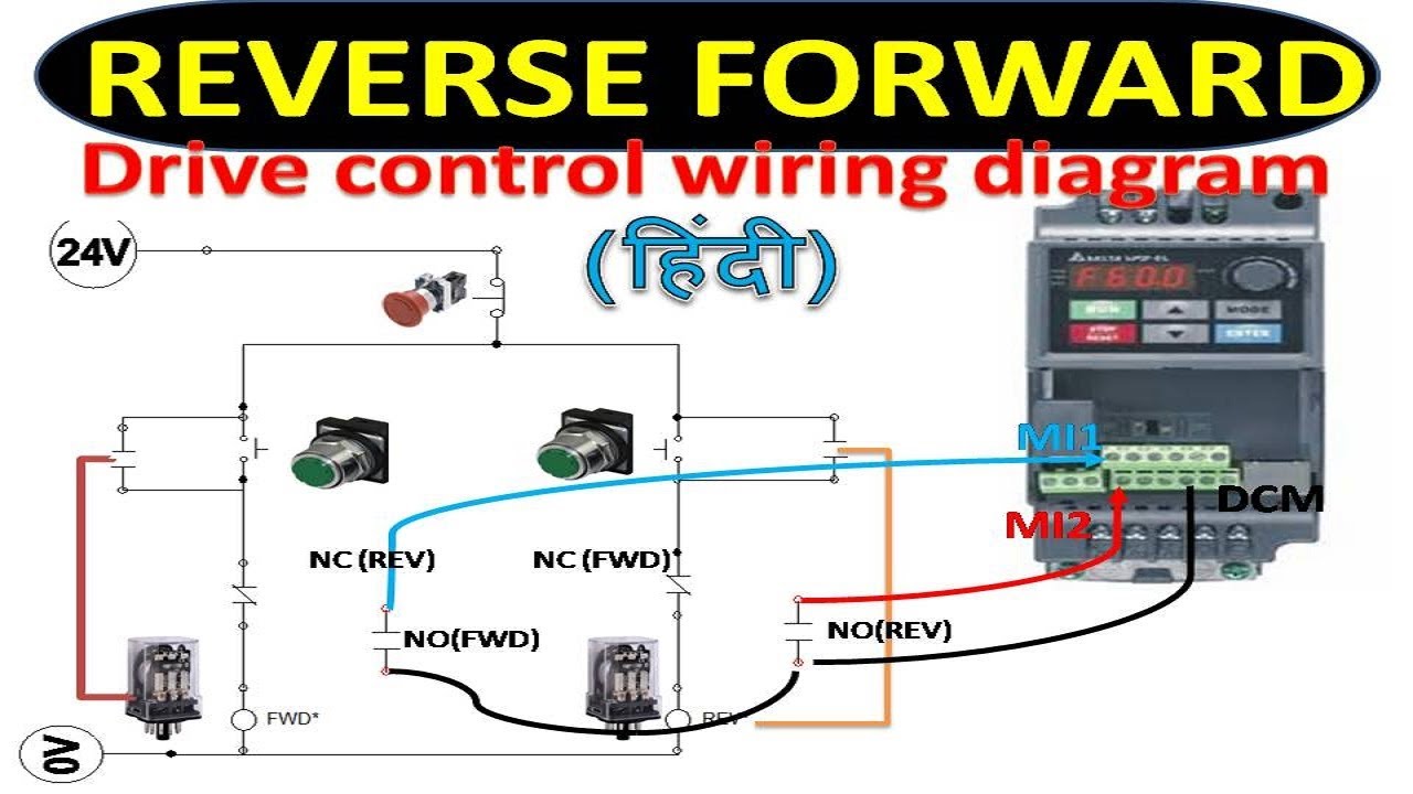
Vfd starter wiring diagram. When you press the on push k1 contactor will hold and k1 no1 become nc. Vfd start stop wiring diagram. Its supposed to assist all of the average user in developing a proper method. We strongly recommend using a certified electrician to set up your vfds. The vfds showed in the video are the d720s 230v single phase and the d720 230v three phase. Learn the basic wiring of variable frequency drives vfd with our electrician steve quist.
Wiring diagram will come with a number of easy to follow wiring diagram guidelines. A wiring diagram is a streamlined standard photographic depiction of an electric circuit. These directions will likely be easy to understand and implement. A wiring diagram is a streamlined conventional photographic depiction of an electrical circuit. It reveals the elements of the circuit as streamlined shapes and also the power and signal connections between the devices. In this video we used the very popular mitsubishi d700 series vfd showing single phase and three phase wiring instructions.
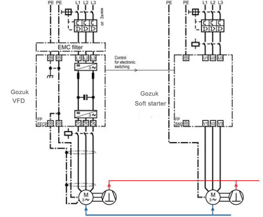
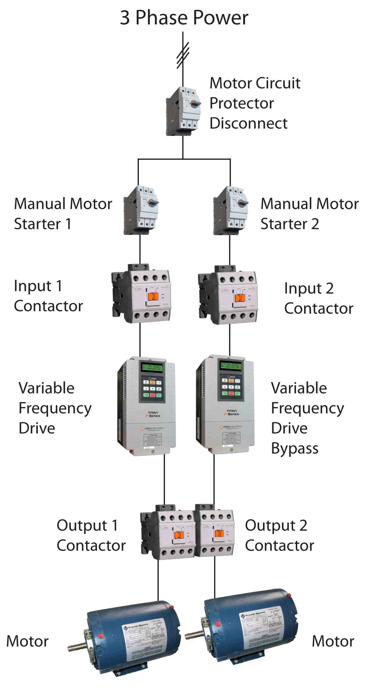
Wiring diagram vfd bypassstar delta starter schematic at discrd vfd wiring diagram. It shows the parts of the circuit as simplified shapes as well as the power as well as signal connections in between the tools. Variety of vfd panel wiring diagram. A wiring diagram is a streamlined traditional pictorial representation of an electrical circuit. Connect or do wiring as per vfd side drawing you take 24 v from the vfd pcb directly. K1 no1 pb3 pb4 pb5 should be of potential free contact.
It reveals the components of the circuit as simplified forms and also the power as well as signal connections in between the gadgets.
Gallery of Vfd Starter Wiring Diagram