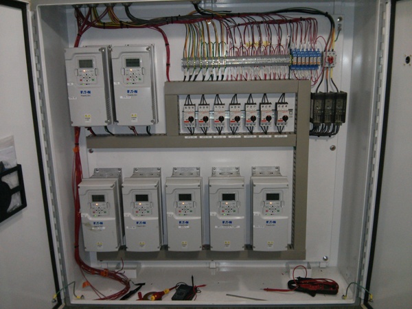
Sometimes your work space is dusty dirty wet humid corrosive or hot. You need a vfd control panel an enclosure that protects the vfd and other electric components.

How To Construct Wiring Diagrams Industrial Controls
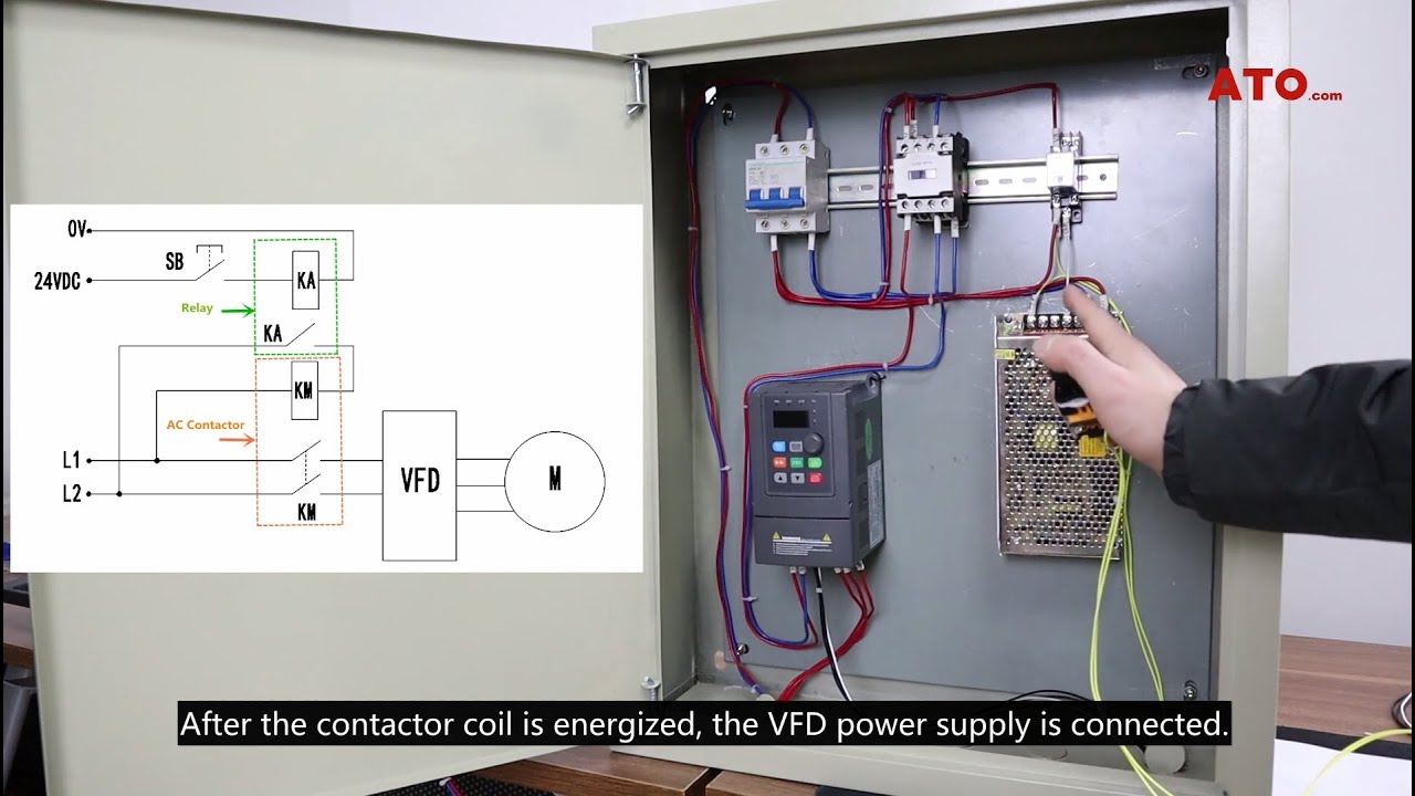
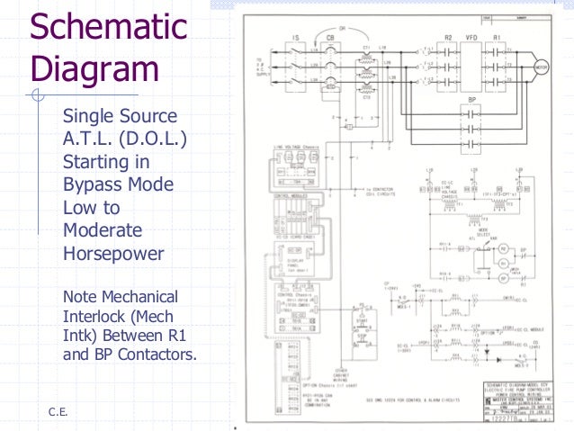
Vfd control panel wiring diagram. When you press the on push k1 contactor will hold and k1 no1 become nc. However one can refer the specific wiring diagram of thier vfd and can make vfd. By headcontrolsystem variety of vfd panel wiring diagram. In those harsh environments you cannot just mount your vfd exposed. A wiring diagram is a streamlined conventional photographic depiction of an electrical circuit. Check connections of l1 l2 l3.
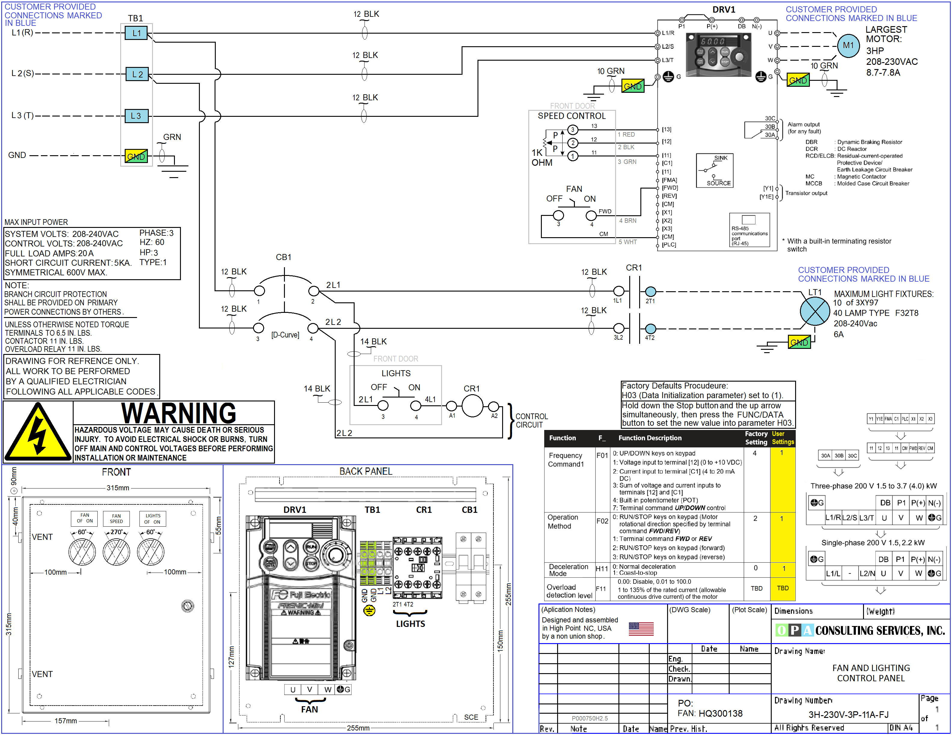
For programming the vfd m. Pin out connection diagram for vfd m fig. Control circuit terminals wiring 1 as the low voltage vfd over current of the control circuit cables is generally small so the size of the control cable can be standardized in order to avoid the interference caused by malfunction the control cables should be twisted shielded wires. T1 t2 t3 used for giving 3 phase input to vfd and connecting motor to it and wires coming out of m0 m1 and gnd. A wiring diagram is a simplified standard photographic depiction of an electric circuit. 2 the control line and the main circuit cable laying.
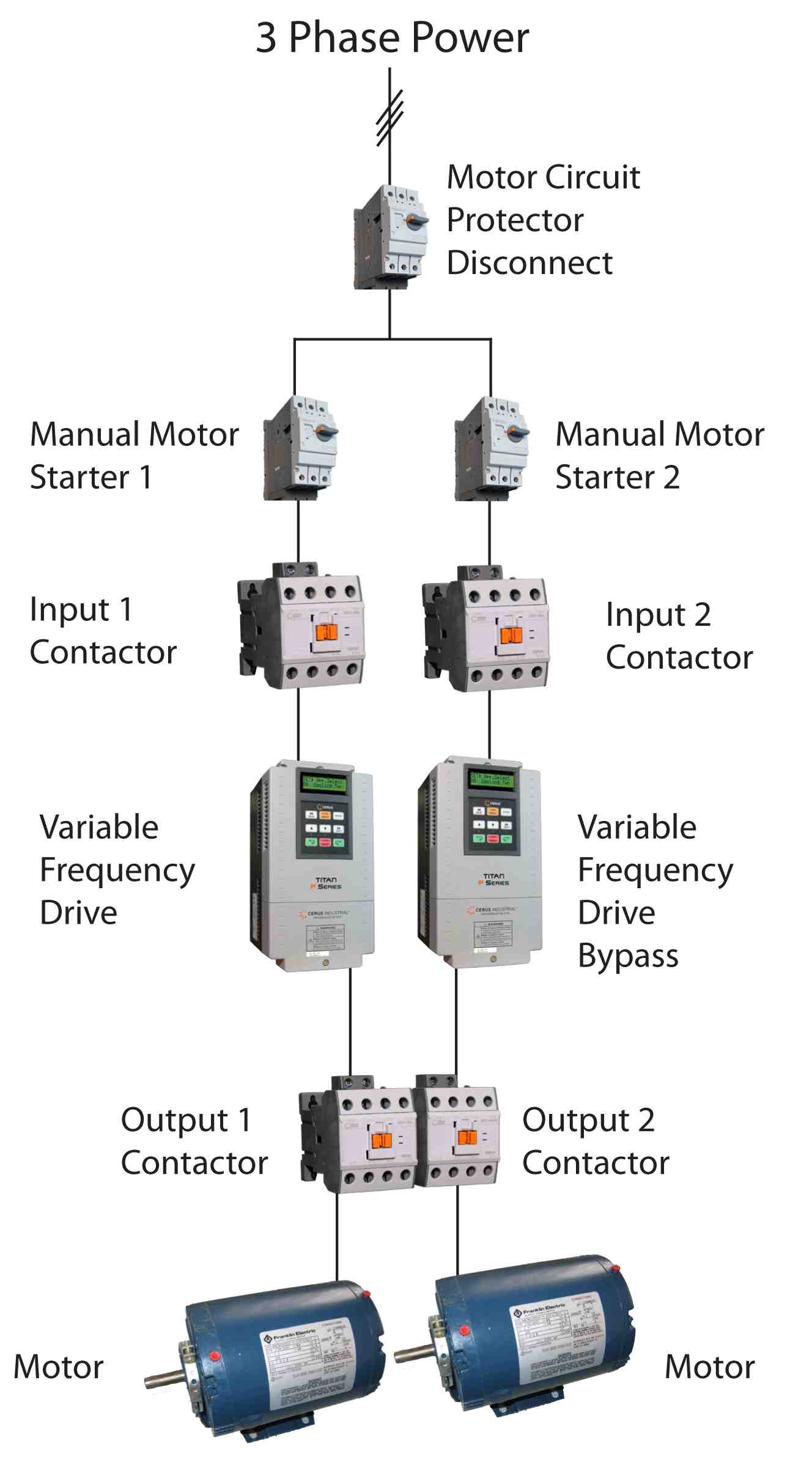
Switch on the 3 phase power supply. It shows the parts of the circuit as streamlined forms and the power and also signal links between the gadgets. K1 no1 pb3 pb4 pb5 should be of potential free contact. Make sure your power wire is rated for the full load amps 14 gage wiring up to 15 amps 12 gage up to 20 amps 10 gage wire up to 30 amps 8 gage wire up to 40 amps 6 gage wire up to 50 amps 4 gage wire up to 70 amps 2 gage wire up to 100 amps and. Assortment of vfd wiring diagram. Vfd start stop wiring diagram.
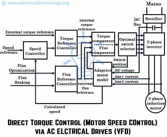
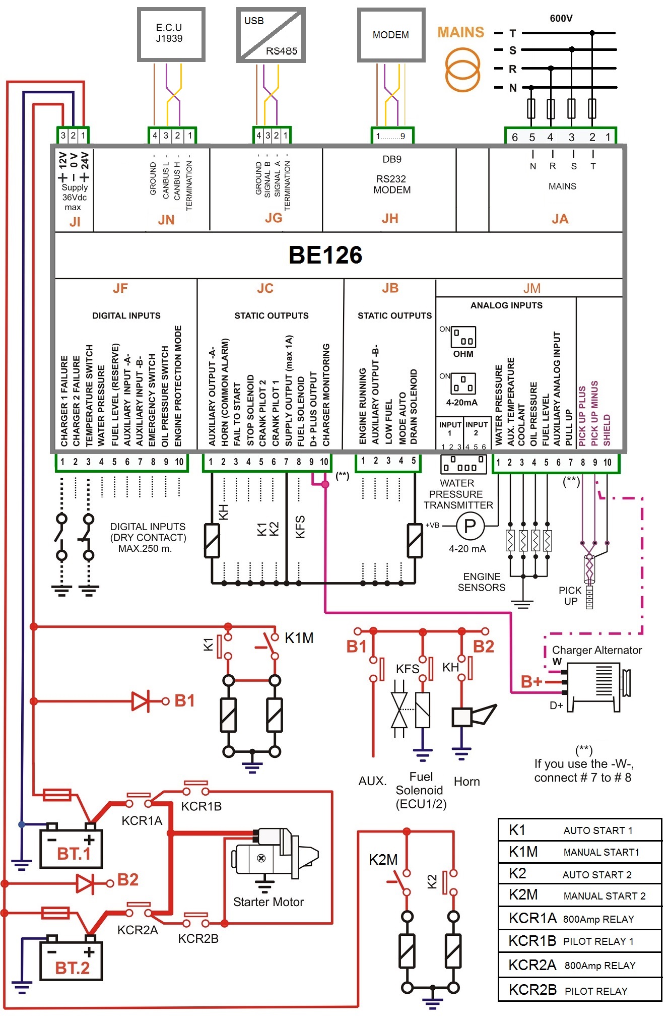
Controlling a digital keypad on delta vfd m steps for complete motor control. Connect or do wiring as per vfd side drawing you take 24 v from the vfd pcb directly. It shows the parts of the circuit as simplified shapes as well as the power as well as signal connections in between the tools. Run wires 3 power wires and 1 ground wire from your breaker panel to your vfd make sure your power wire is rated for the full load amps 14 gage wiring up to 15 amps 12 gage up to 20 amps 10 gage wire up to 30 amps 8 gage wire up to 40 amps 6 gage wire up to 50 amps 4 gage wire up to 70 amps 2 gage wire up to 100 amps and. What is a vfd control panel. Run wires 3 power wires and 1 ground wire from your breaker panel to your vfd.
Though we have not detailed control terminal connection scheme as it will be different for different makes of vfd.
Gallery of Vfd Control Panel Wiring Diagram


.png)