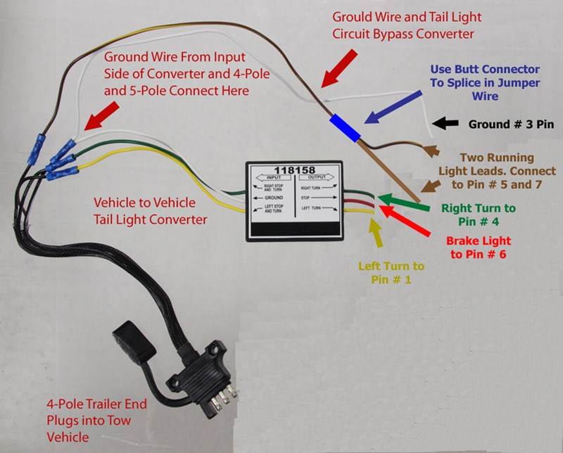
Solve the problem by inspecting the wiring on the trailer to make sure all of the connections are correct and ground wires are connected properly. Below is the generic schematic of how the wiring goes.
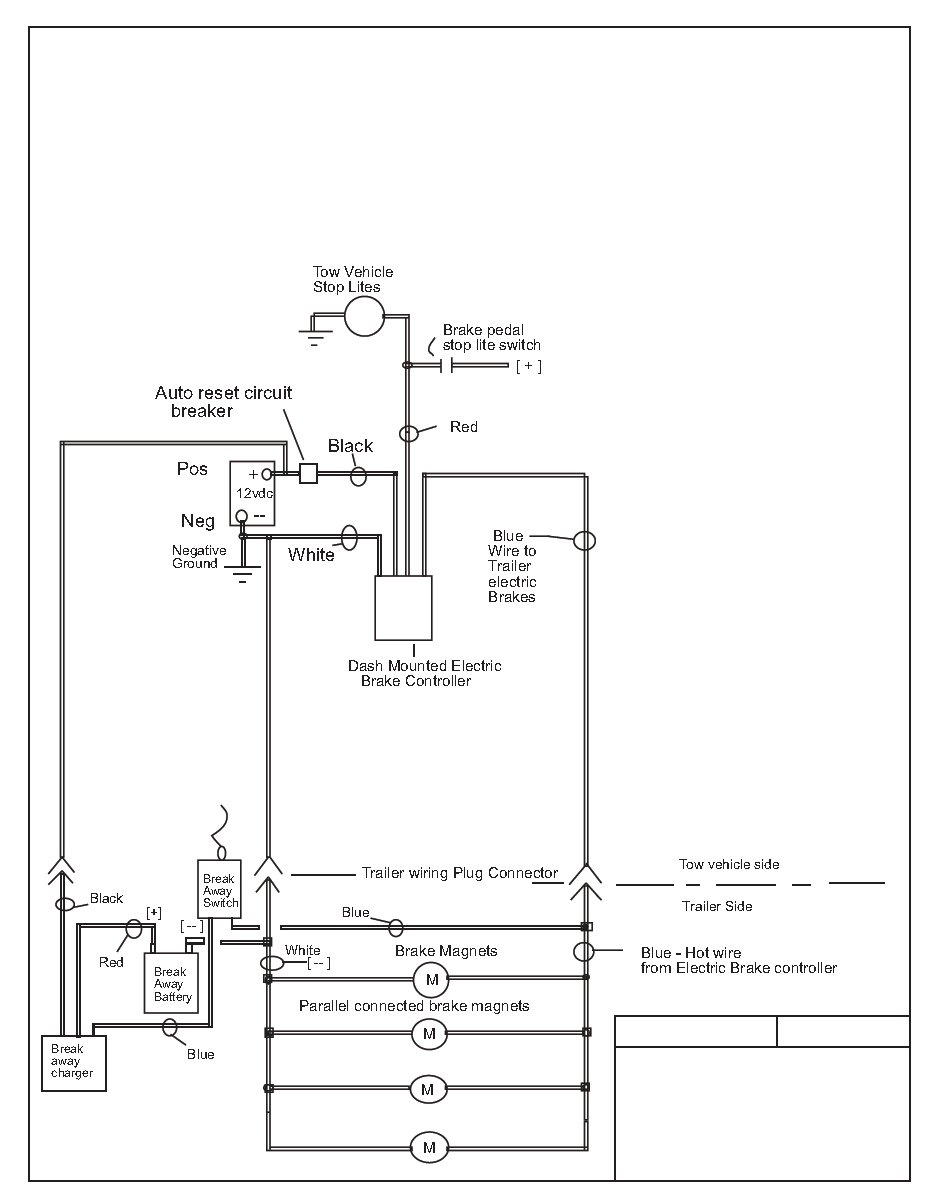
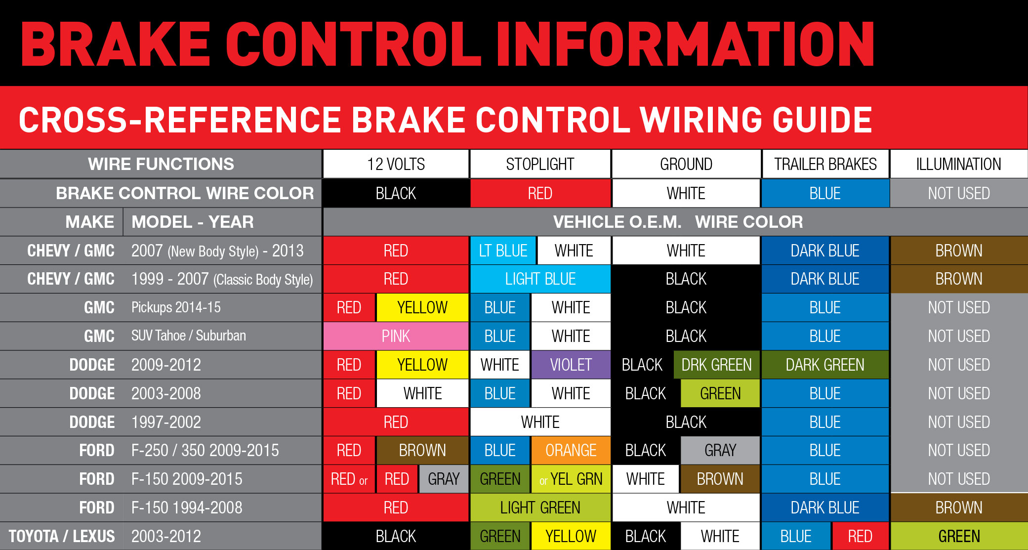
Electric Brake Control Wiring
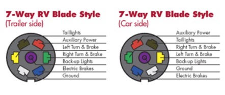
Us trailer wiring diagram. Also it must connect with things if included that use the aux power and back up lights too. This us trailer wiring diagram version is more acceptable for sophisticated trailers and rvs. Collection of travel trailer wiring schematic. Above we have describes the main types of trailer wiring diagrams. As the name implies they use four wires to carry out the vital lighting functions. They also provide a wire for a ground connection.
Complete with a color coded trailer wiring diagram for each plug type this guide walks through various trailer wiring installation solution including custom wiring splice in wiring and replacement wiring. Trailers right turn signal. 4 pin trailer wiring diagram. To connect the electric system of your trailer to the vehicle you will be using special connector. Vehicle ground point metal uncoated rustproof. Most likely the ground wire on the trailer is not secured properly.
A signal is going in and coming out on the appropriate wires then there is a problem with the trailer wiring. Left turn of vehicles wiring harness. Trailer ground point metal uncoated rustproof. It can transfer electricity better so the connector is suggested for higher level electric in the vehicle. Some trailer builders just connect this wire to the frame then connect the ground from all the other lights and accessories to the frame as well. Taillight of vehicles wiring harness.
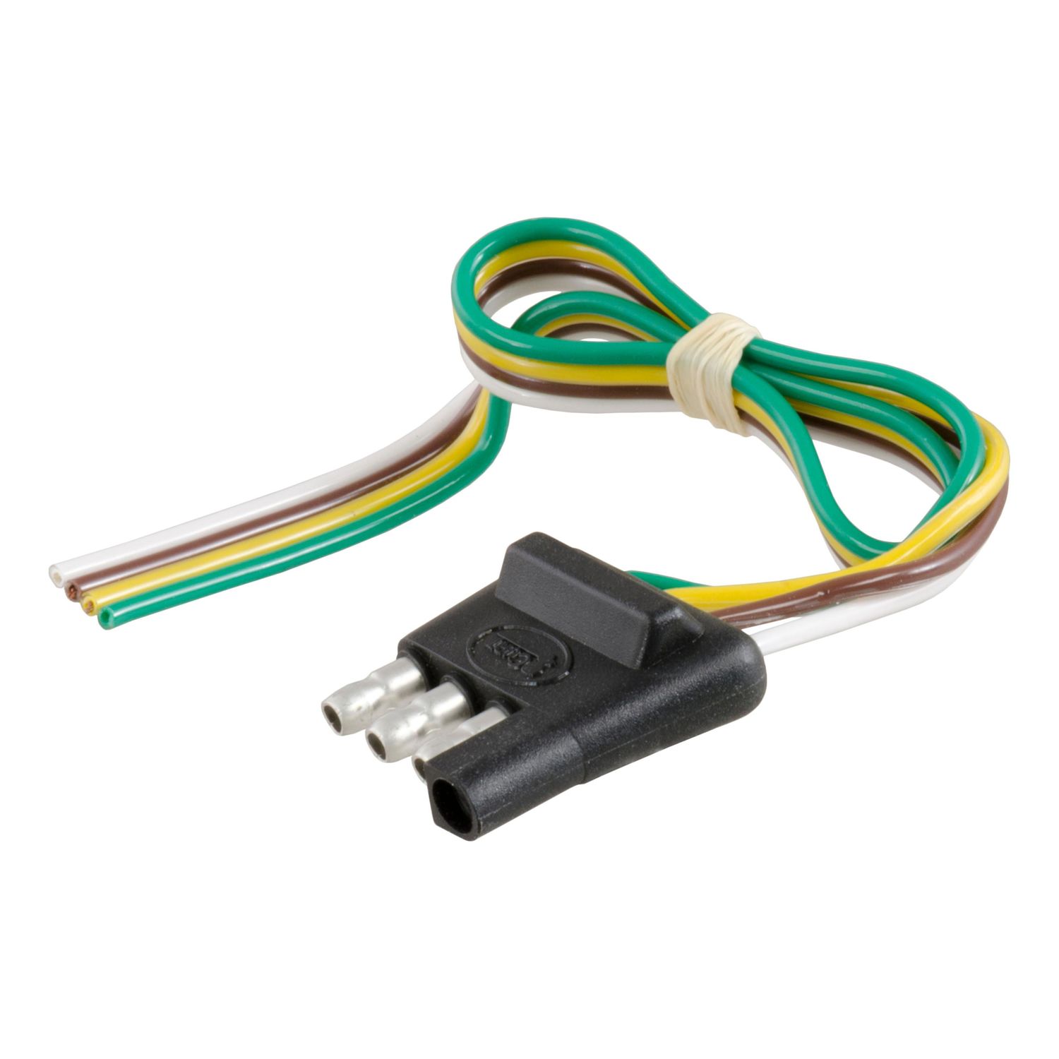
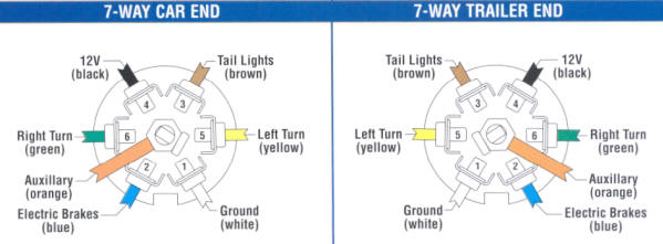
If you are looking at the inside of the trailer connector where the wires mount to the terminals starting at the top and rotating clockwise. Right turn of vehicles wiring harness. The trailer wiring diagram shows this wire going to all the lights and brakes. White pin to your ground. Right turn signal stop light green left turn signal stop light yellow taillight license side marker brown and a ground white. 4 way tow vehicle side.
The four wires control the turn signals brake lights and taillights or running lights. Trailer wiring diagrams 4 way systems 4 way flat molded connectors allow basic hookup for three lighting functions. 4 way trailer connectors are typically used on small trailers such as boat snowmobile utility and other trailers that that do not use brakes. 4 way trailer connectors are. We have an excellent wiring diagram on our website i will provide you a link so you can look at it. A wiring diagram is a streamlined traditional photographic depiction of an electric circuit.
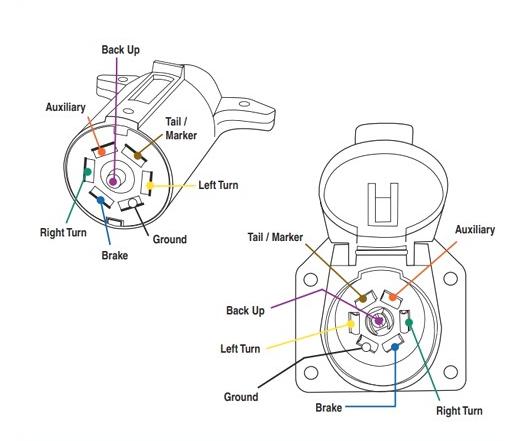
If your vehicle is not equipped with a working trailer wiring harness there are a number of different solutions to provide the perfect fit for your specific vehicle. It reveals the parts of the circuit as streamlined shapes as well as the power and also signal links in between the gadgets. When wiring a trailer connector it is best to wire by function as wire colors can vary. Heres the diagram for 7 pin connector. Trailers left turn signal.
Gallery of Us Trailer Wiring Diagram


/trailer-wire-colors-589d62645f9b58819cf8721f.gif)