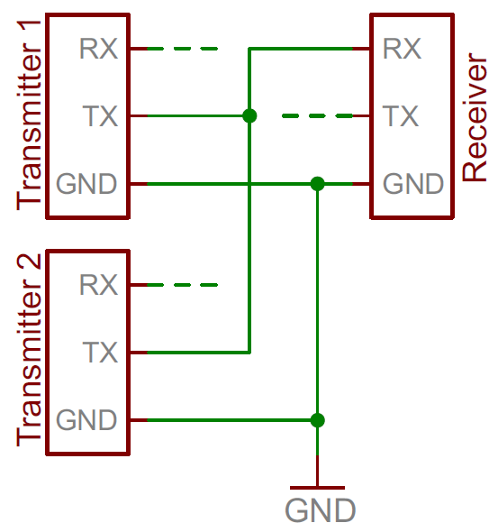
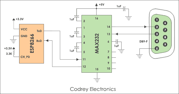
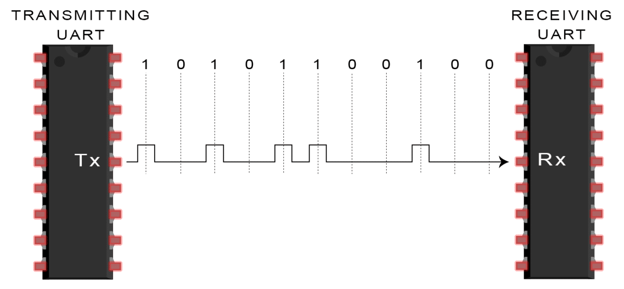
The cable may be utilized to transfer information from 1 apparatus to another. Basic uart connection diagram one wire is for transmitting data called the tx pin and the other is for receiving data called the rx pin.
C Rome B Tutorial For Uart Logging
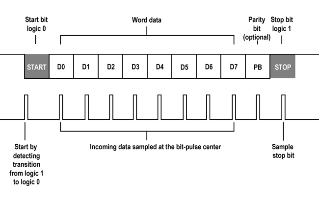
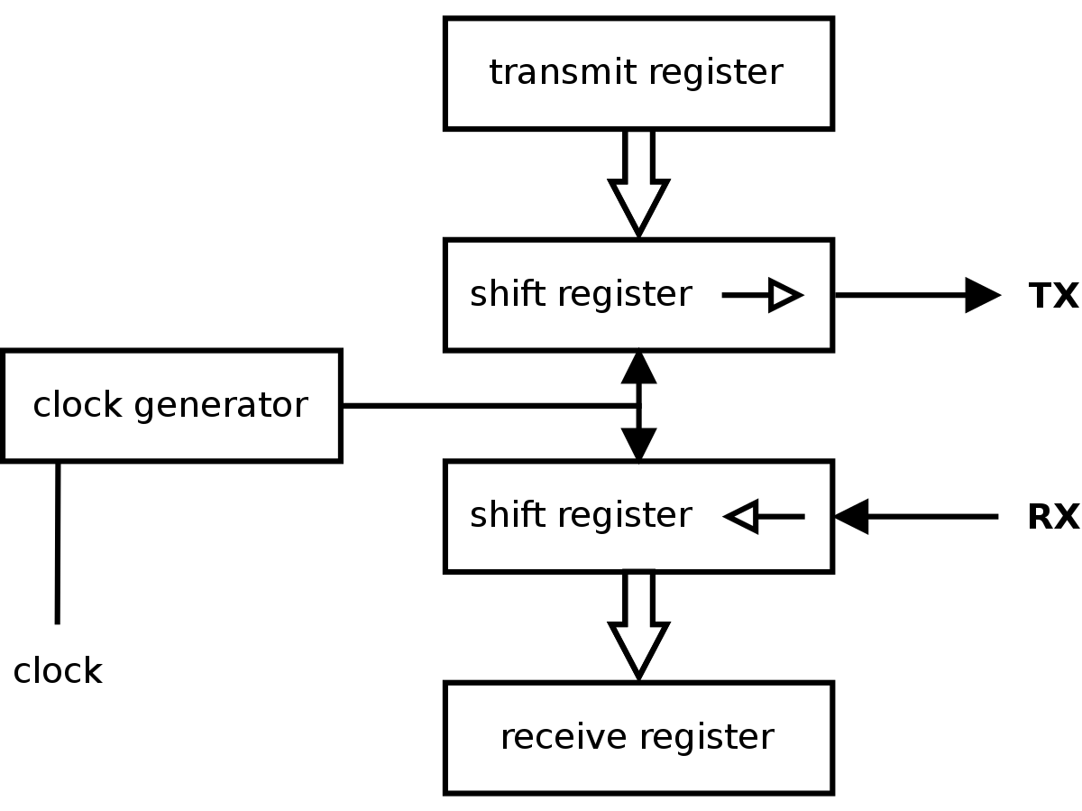
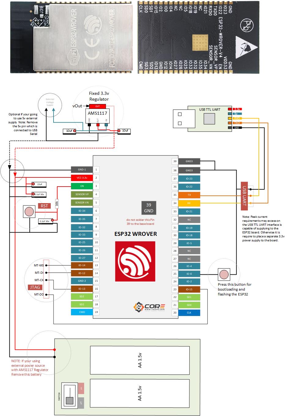
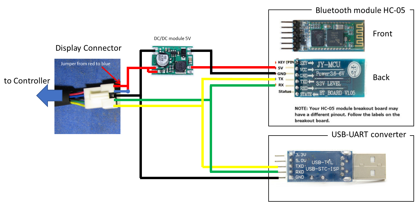
Uart wiring diagram. Uart block diagram the uart block diagram consists of two components namely the transmitter receiver that is shown below. Usb to uart cable wiring diagram there are a number of kinds of electronic gadgets out there. Solder your runcam racermicro eaglemicro swift 3 to one of the uart ports on your flight controller as showed in above diagram. Below is a timing diagram for the transmission of a single byte. Figure 1 shows a basic uart connection diagram. We can only connect two uart devices together.
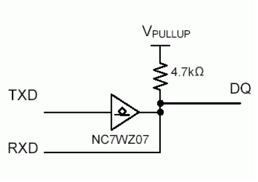
Likewise the receiver section includes a receive hold register shift register and control logic. Firmware version should be. When uart has finished transfer uart de asserts busy signal system de asserts send signal. In addition it can link device to a power supply for charging purpose. The transmitter section includes three blocks namely transmit hold register shift register and also control logic. The reader is reminded that the uart serves as the bus master and therefore begins all bit transfers on a high to low transition of the txd output.
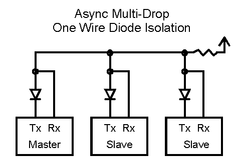
Most of them use usb cable. Single wire for each direction plus ground wire relatively simple hardware. 1 wireuart bit timing the timing diagrams in figures 4 through 8 describe the relationship between 1 wire time slots and uart byte frames.
Gallery of Uart Wiring Diagram