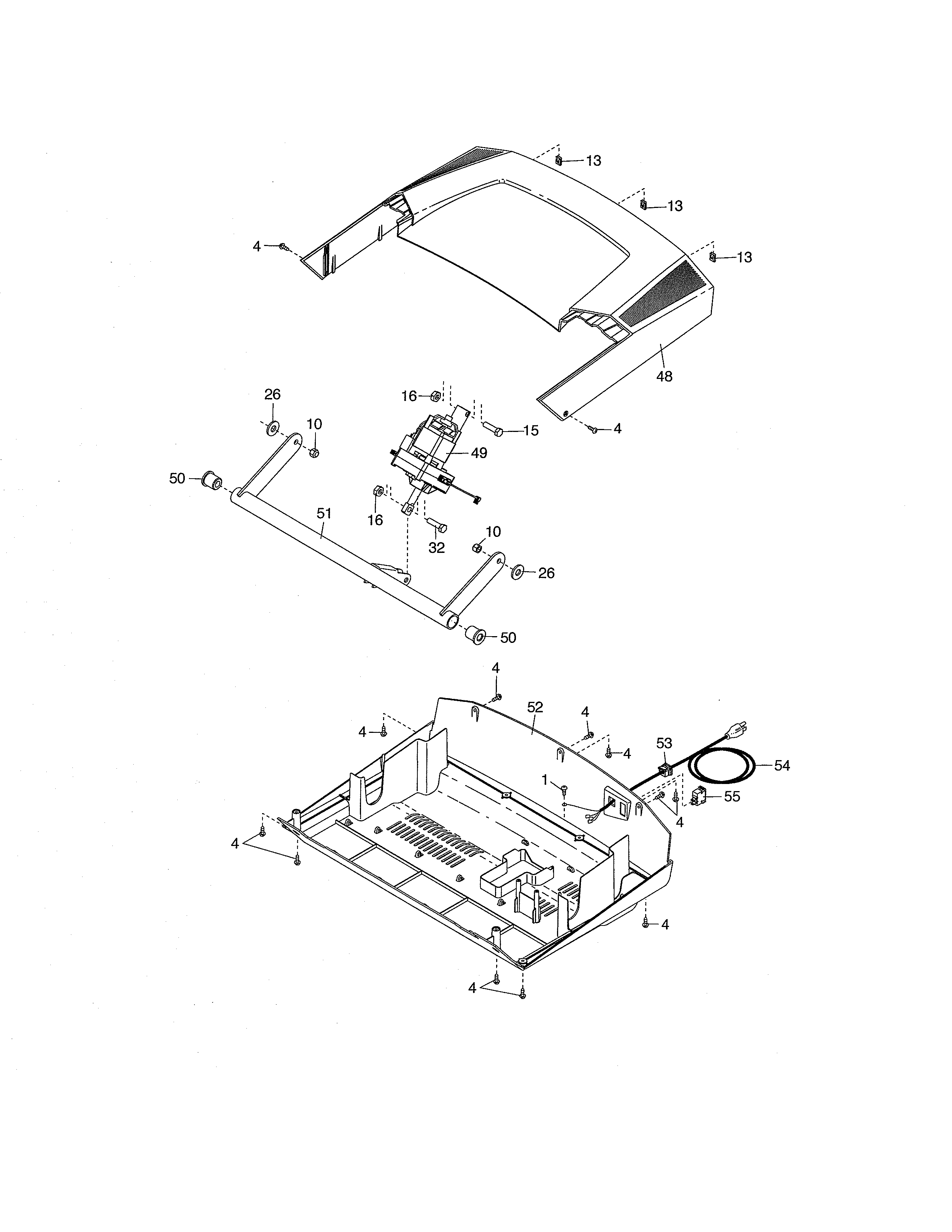
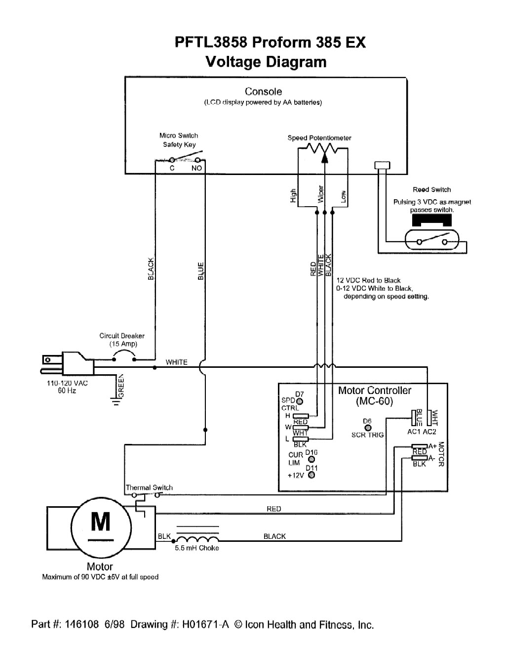
Direct responce to mrpete222 here is a really quick video of how to use a treadmill motor and the basic functions of the control board. I have the wiring diagram and the users manual but neither show how the wires connect.

Bz 4623 Treadmill Circuit Board Wiring Diagram Download Diagram
Treadmill incline motor wiring diagram. Penn fitness 954 views. Treadmill wiring diagram wiring diagram is a simplified tolerable pictorial representation of an electrical circuitit shows the components of the circuit as simplified shapes and the capability and signal associates surrounded by the devices. Requested video on how to wire up an incline motor assembly from a treadmill. Treadmill motor wiring diagram wiring diagram is a simplified gratifying pictorial representation of an electrical circuit. One was the motor controller and the other was for the display and linear actuator that changed the incline. Mine had 2 circuit boards.
Incline motor white 16 connect with controller com voltage110v 120v transfermersmall end 20 conncet with controller v l voltage8v big end 21 connect with controller v h voltage110 120v 18v motor red 11 connect with controller m below 100v motor black 12 connect with controller m below 100v. What to cut what to plug what to wire. Mine had 2 circuit boards. Yes move on to next step wire harness and control panel are ok. Page 15 symptom probable cause possible short in circuit treadmill wiring. I had an older treadmill that matched the wiring diagram vitamaster8711bppdf and it works great.
Incline motor drawing treadmill down bad pwm too much tension on belt or obstruction belt. Vision treadmill incline motor replacement duration. Weakened circuit breaker or high beltdeck friction support services 800 883 8783 corrective action. With treadmill in calibration mode page 16 set speed at 4 mph check vdc across mtr 1 and mtr 2 with the motor leads connected to the motor the voltage should measure 10 vdc for every 1 mph. A wiring diagram usually gives suggestion about the relative incline and contract of devices and terminals upon the devices to encourage in building or servicing the device. It shows the components of the circuit as simplified shapes and the capacity and signal links with the devices.
Refer to wiring harness diagram for your model. All 5 wires 2 black 2 red and 1 white going to the incline motor were disconnected and the bolt connecting the incline motor drive shaft to the frame was gone. Breaker trips motor issues.


