Wiring a table fan motor with capacitor electrical question. If controls have been factory mounted a wiring diagram will be included with the unit indicating the factory mounted components.

Holley Performance Products Forums
Table fan wiring diagram pdf. It should be similar to the schematics above. This might seem intimidating but it does not have to be. With these diagrams below it will take the guess work out. I have a bionaire brand table electric fan. I am rewiring a table fan speed control switch. The colors of the wiring used in my fan may be different from yours so make a note.
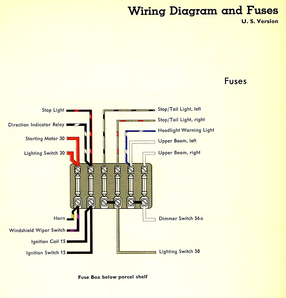
These diagrams are current at the time of publication check the wiring diagram supplied with the motor. Table fan fan pdf manual download. Universal electronic fan timers application the st9120u universal electronic fan timers integrate control of all combustion blower and circulating fan operations in a gas warm air appliance. View and download hunter table fan owners manual online. Ceiling fan wiring diagram. The product has good stability impact resistance current overload and strong low loss hig.
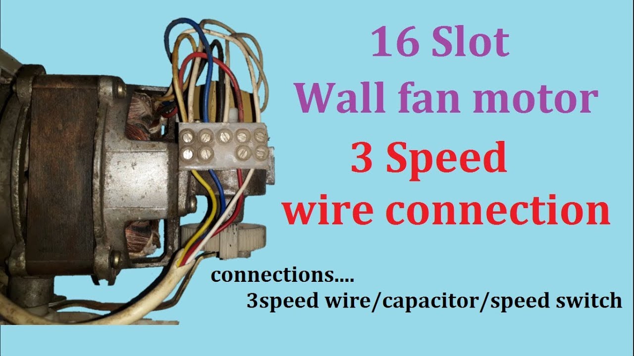
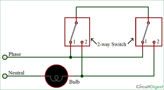
Troubleshooting the thermal fuse. Pick the diagram that is most like the scenario you are in and see if you can wire up your fan. Hunter 12 inch high performance oscillating table fans owners guide. The electric motor is a bm 122 decomin brand 3 speed motor. Suggested electric fan wiring diagrams suggested primary cooling fan single speed onoff using 12 volt switching devices only for primary activation note. 3ø wiring diagrams 1ø wiring diagrams diagram er9 m 3 1 5 9 3 7 11 low speed high speed u1 v1 w1 w2 u2 v2 tk tk thermal overloads two speed stardelta motor switch m 3 0 10v 20v 415v ac 4 20ma outp uts diagram ic2 m 1 240v ac 0 10v outp ut diagram ic3 m 1 0 10v 4 20ma 240v ac outp uts these diagrams are current at the time of publication.
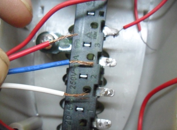
It has a 3 speed fan motor. Take your time to trace the wiring and note down its color and location. Disconnect power to the fan. There are 6 wires. The basic purposes of the. Most stand alone adjustable thermostats ie.
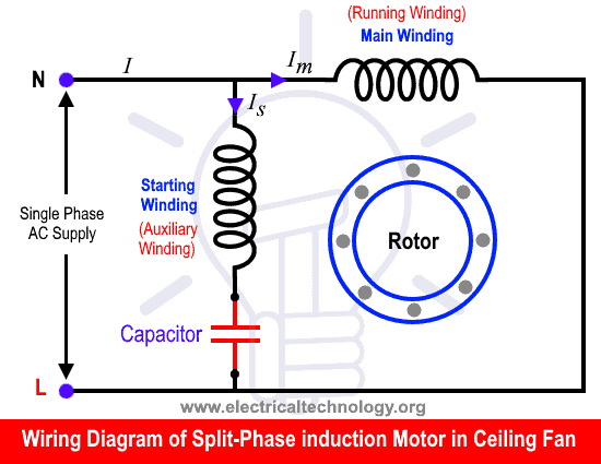
Inst maint wiring5qxd 20112015 1137 am page 7 9. Open up the control unit cover. Ceiling fan wiring diagram capacitor1. Hayden flex a lite or perma cool brands can provide a 12 volt output when activated. Abs or polypropylene shell 2. High quality ceiling fan wiring diagram capacitor.
For field wiring of room sensors and other accessories refer to the controls contractors documentation for all wiring information. This control is the central wiring point for most of the electrical components in the furnace. Take a closer look at a ceiling fan wiring diagram.
Gallery of Table Fan Wiring Diagram Pdf