To charge at c1this takes time to fully charge and when a. Wiring diagrams for surge arresters wiring of 1 and of 3 x dehnguard 275 and 1 x dehngap ct.
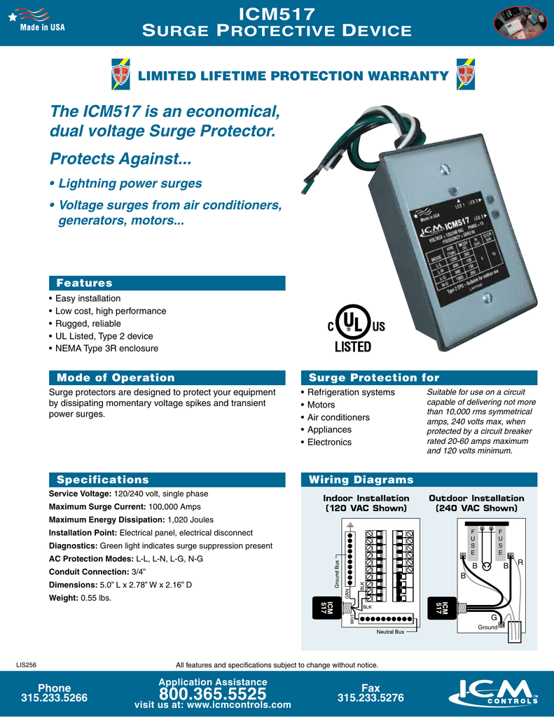
Ts 275m5rm Class D Surge Protector China Ts 275m5rm Class D
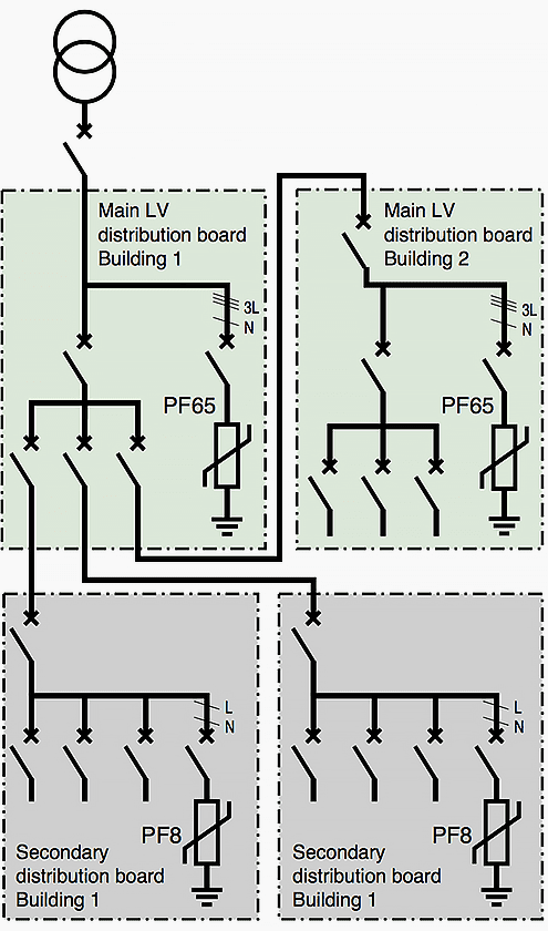
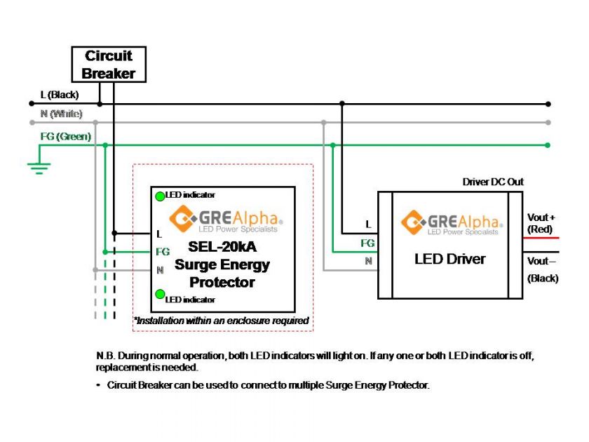
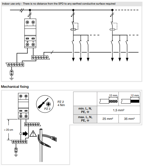
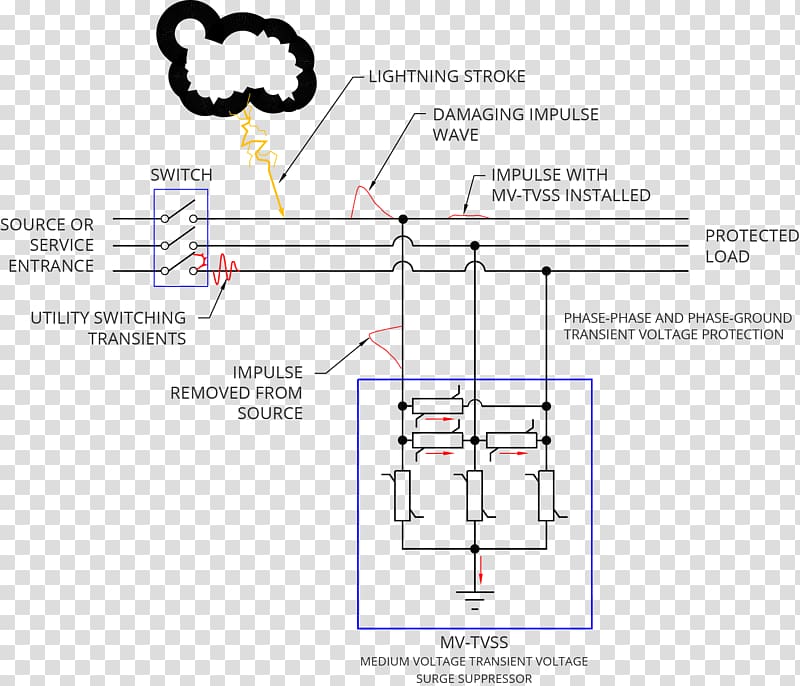
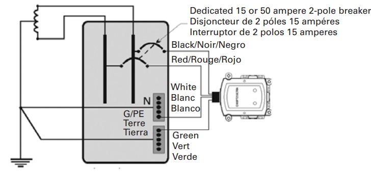
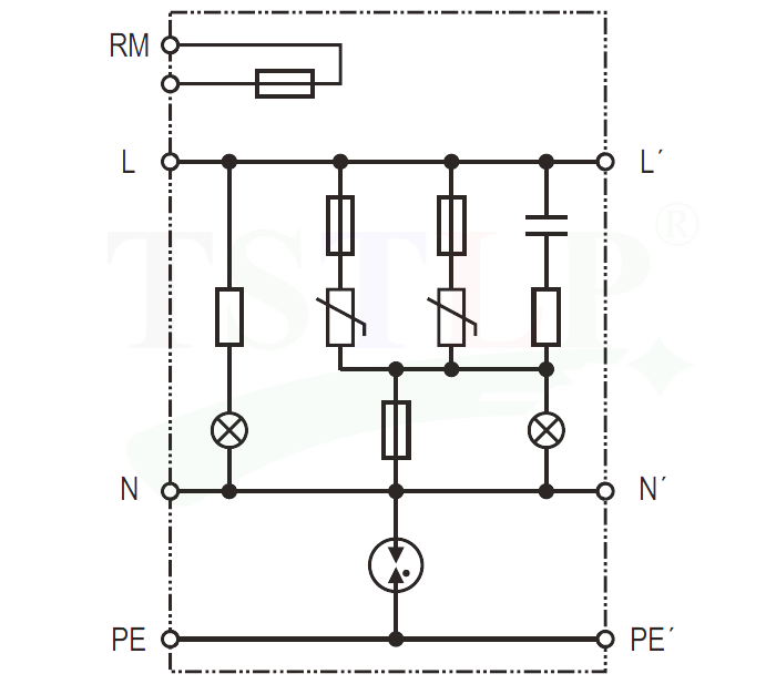
Surge protection wiring diagram. Collection of 3 phase surge protector wiring diagram. After working set to prevent equipment damage from pressure. A wiring diagram is a streamlined traditional pictorial depiction of an electrical circuit. It shows the components of the circuit as simplified shapes and also the power and also signal links between the devices. Surge protection devices modular pluggable and high capacity surge protection solutions for commercial and industrial applications. See the diagram to the right from iec 63205 1 standard which displays the dispersion of the highest lightning considered.
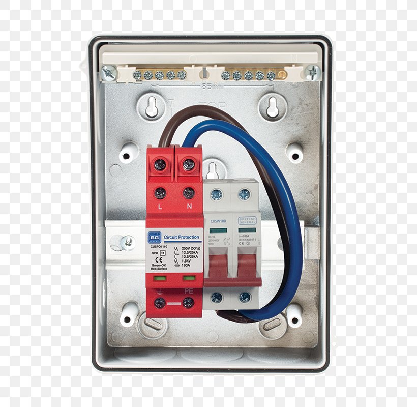
Assortment of surge protector wiring diagram. Class 1 and class 2 protection for 380vac. Installation of class 1 and class 2 for 3 phase. It reveals the components of the circuit as simplified shapes and the power as well as signal connections in between the tools. This circuit can be used to delay other appliances connected to the output of the relay. A wiring diagram generally provides info about the relative placement as well as arrangement of tools and terminals on the devices to aid in structure or servicing the tool.
Surge protector circuit diagram the connection of this circuit can be done among the live mains lead that usually doesnt have a flow of current. A wiring diagram is a simplified traditional photographic representation of an electrical circuit. Installation of class 1 and class 2 single phase. The ic number is 4011 nand gate cmos when switch s1 is current through r1. Installation of class 1 and class 2 for 3 phase. But when the voltage among the terminals is upper than the voltage rating amount of gdt varistor then the flow of current will be there through the used components.
Protection surge with delay the relay using ic 4011.
Gallery of Surge Protection Wiring Diagram