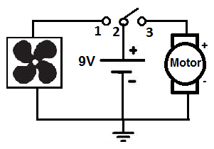
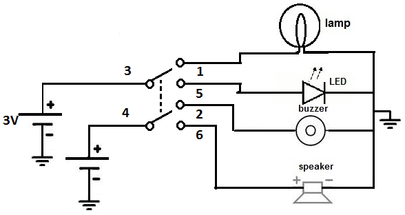
Below is the schematic diagram of the wiring for connecting a spdt toggle switch. So a spdt switch can power either one of 2 circuits.

Slide Switch Precise Information And Various Applications Of
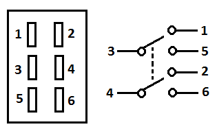
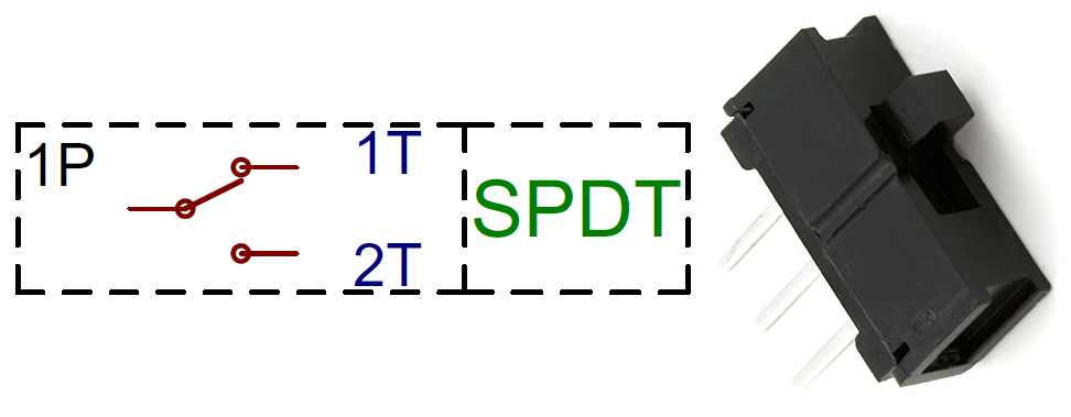
Spdt slide switch wiring diagram. Below is the schematic diagram of the wiring for connecting a spdt toggle switch. The 2 coil terminals is where the voltage is placed in order to energize the coil. Hopefully it could save some people the hassle of having to rewire their project. A spdt toggle switch has 3 terminals. One common pin and two pins which vie for connection to the common. An spdt switch circuit symbol and an spdt slide switch.
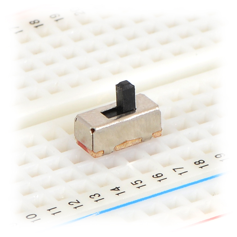
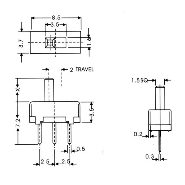
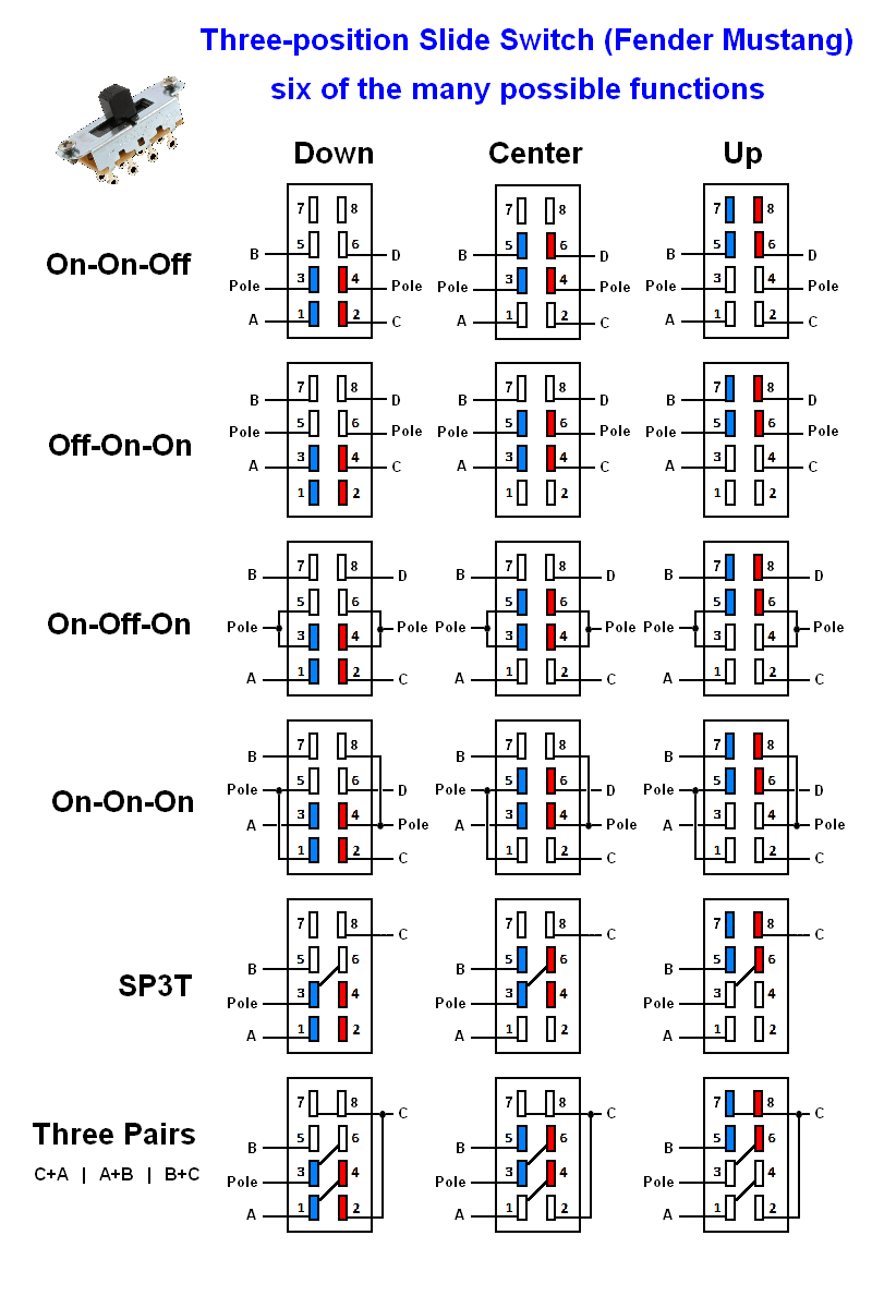
One of the most common pieces of circuit bending hardware is the single position dual throw spdt switch. With slide switches the switching movement is in a linear to and fro fashion. I recently ran into a wiring problem and made an illustrated post on how i figured out the solution and some guesses as to why i came to the solution i did. And terminal 3 can connect to any load to power any device. And terminal 3 can connect to any load to power any device. Terminal 1 can connect up to any load to power a certain device.
Spdts are great for selecting between two power sources swapping inputs or whatever it is you do with two circuits trying to go one place. Most simple slide switches are of the spdt variety. Another common switch type is the spdt. Terminal 2 is the terminal which receives the power necessary so that the loads on terminals 1 and 3 can be powered. We will now go over the wiring diagram of a spdt toggle switch. Single pole double throw spdt relay wiring diagram this is the diagram below to learn all the pin terminals of a single pole double throw spdt relay.
A spdt toggle switch has 3 terminals. Terminal 1 can connect up to any load to power a certain device. Spdts have three terminals. Below is the schematic diagram of the wiring for connecting a spdt toggle switch.
Gallery of Spdt Slide Switch Wiring Diagram