Single phase motors controls 12 1 hp crc qd relay 282 40 5015 sixth digit depends on hp control box wiring diagrams gnd green cap capacitor b l1 b main y r start l2 l1 motor leads line leads orange qd relay black yellow red blue gnd green gnd green gnd green start capacitor run capacitor cap. Single phase motor forward reverse wiring diagram certainly provide much more likely to be effective through with hard work.
Induction Motor Circuit Diagram Pdf Equivalent Circuit Of
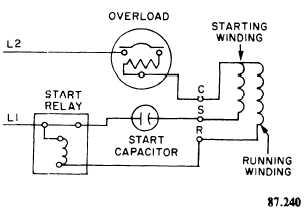
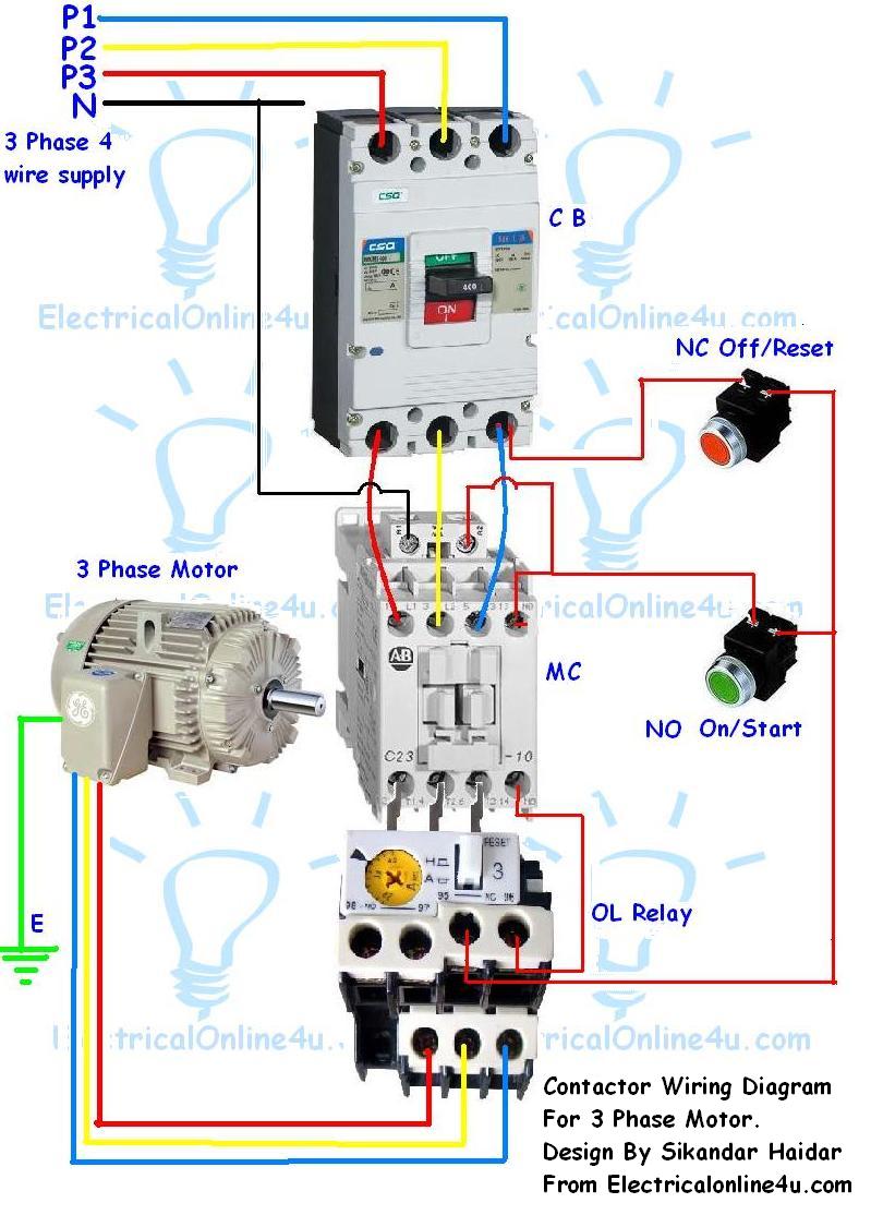
Single phase motor wiring diagram pdf. Just as in the three phase motor diagram the motor shows the power supply lines as being identified with the t. Two speed motors for all other single phase wiring diagrams refer to the manufacturers data on the motor. See mg 1 221 mg 1 224 direction of rotation. The reconnection must be carried out by. For most shore facility applications this is the case. 2 11 in which vector 1 is 120 degrees in advance of vector 2 and the phase sequence is 1 2 3.
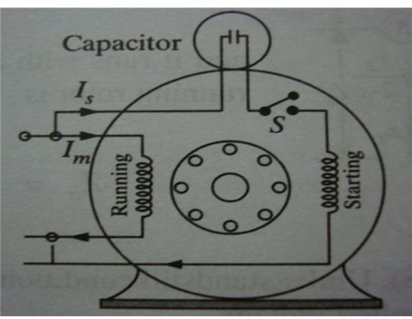
The basic diagram view a shows a circle with two leads labeled t1 and t2. Wiring diagram single phase motors 1empc permanent capacitor motors 1empcc capacitor start capacitor run motors electric motors limited when a change of direction of rotation is required and a change over switch is to be used it will be necessary to reconnect the termination on the terminal block. For everyone whether you are going to start to join with others to consult a book this single phase motor forward reverse wiring diagram is very advisable. And you should get the single phase motor forward reverse. Diagram dd6 diagram dd7 m 1 ln e diagram dd8 ln e l1 l2 l3 sc z1 u2 z2 u1 cap. Thermal contacts tb white m 1 z2 yellow z1 blue u2 black u1 red bridge l1 and l2 if speed controller sc is not required m 1 ln e white brown.
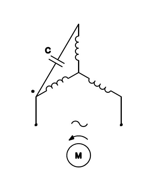
Schematic diagrams for the single phase motors. In many cases the single phase motors on board a. Terminal markings and internal wiring diagrams single phase and polyphase motors meeting nema standards see fig.
Gallery of Single Phase Motor Wiring Diagram Pdf