Image result for fg wilson control panel wiring diagram pdf. Thats the key difference between series and parallel.

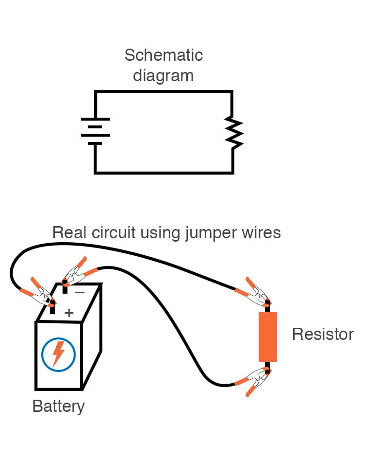
How To Read A Schematic Learn Sparkfun Com
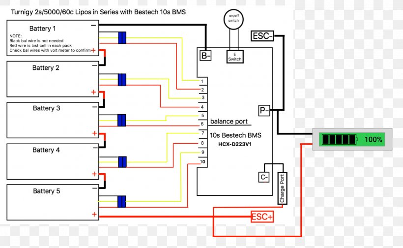
Series board wiring diagram. Two components are in series if they share a common node and if the same. Circuit diagram of leds in series. If you like this video like comment and share with your friends. The following image shows the circuit diagram of the leds in series. Since the leds are connected in series the current through all of them will be the. The following explanation will help you understand better how to design home wiring layouts.
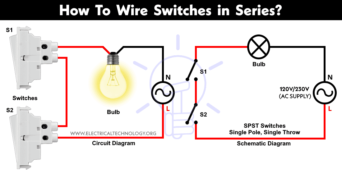
Brown phaseor line blue neutraland green earth conductor. Here you can see there is a cut in the line wire connected to lamp 3 so the bulb is switch off and the rest circuit is working. How to wire a switch and a load a light bulb to an electrical supply. The series control panel allows the generating set to be automatically controlled by a remote signal and is therefore suitable for controlling a standbyseries control panel fgwilson service fg. Its likely though youve already read the wikipedia page about series and parallel circuits here maybe a few other google search results on the subject and are still unclear or wanting more specific information as it pertains to leds. 5mm white leds x 3.
Connect your neck pickup to the pigtail labeled n and your bridge pickup to the pigtail labeled b. This is simple diagram of series board but we can not test low resistance appliances electrical devices however my incoming post will be about the series board for low resistance appliances testing. As can be seen in the diagram the wiring is pretty simplethe phase is invariably applied to one terminal of the switch the other terminal moves to one of the connections of the load and the other. Grey phase 1 or line1 black line 2 brown line 3 blue neutral and green earth conductor. 4 printed circuit board assemblies and wiring aiding reliability and ease of service. The uses and advantage of series testing board in unlimited and we can use it for many thing.
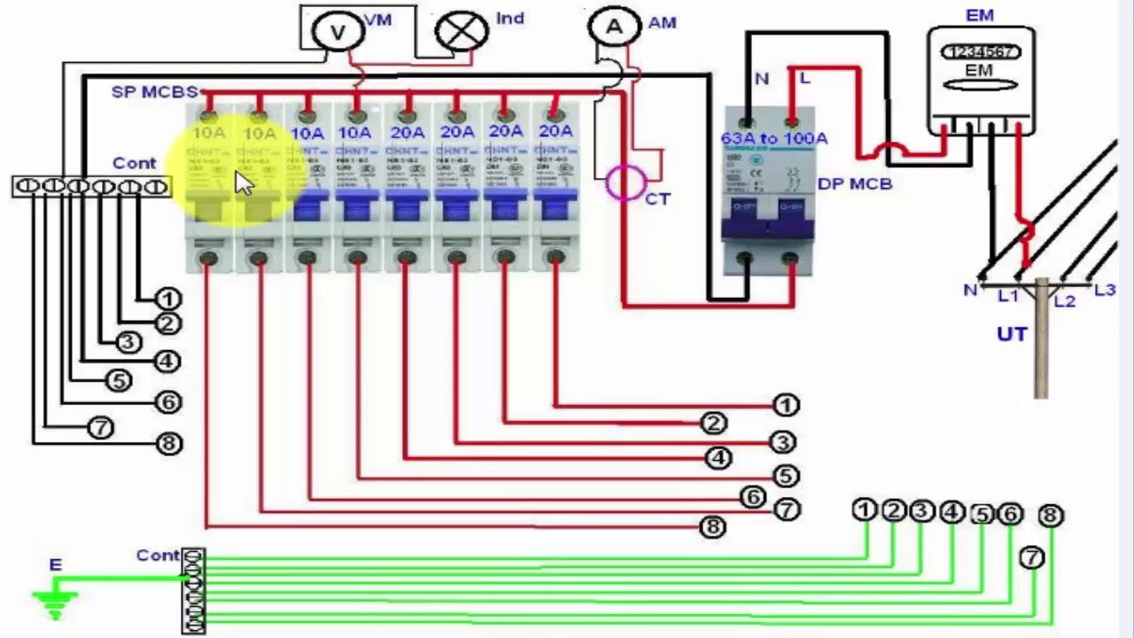
We can test the condactor by using this board. Dont forget to subscribe. Below is the given wiring diagram of single phase distribution board with rcd in both nec and iec electrical wiring color codes. Designing home wiring layouts. Series board wiring diagram in this video im show youseries board wiring diagram. Components required for leds in series.
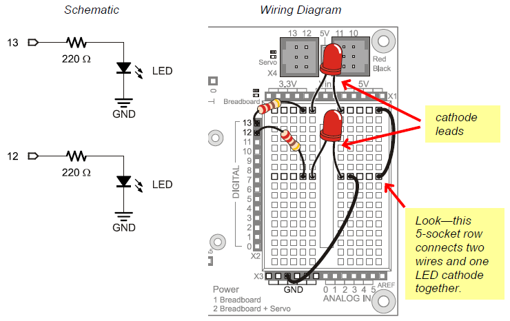
47ω resistor 14 watt 12v power supply. Three phase 208 ac. Es 335 prewired standard assembly p gmod 6. Notice that in some nodes like between r 1 and r 2 the current is the same going in as at is coming outat other nodes specifically the three way junction between r 2 r 3 and r 4 the main blue current splits into two different ones. Each wiring diagram is shown with a treble bleed modification a 220kω resistor in parallel with a 470pf cap added to the volume pots. Another major defect of series lighting circuit is that as all lamps or bulbs are connected between line l and neutral n accordingly if one of the light bulb gets faulty the rest of the circuit will not work as the circuit will be open as shown in fig below.
Hopefully those looking for practical information on electrical circuits and wiring led components found this guide first.
Gallery of Series Board Wiring Diagram