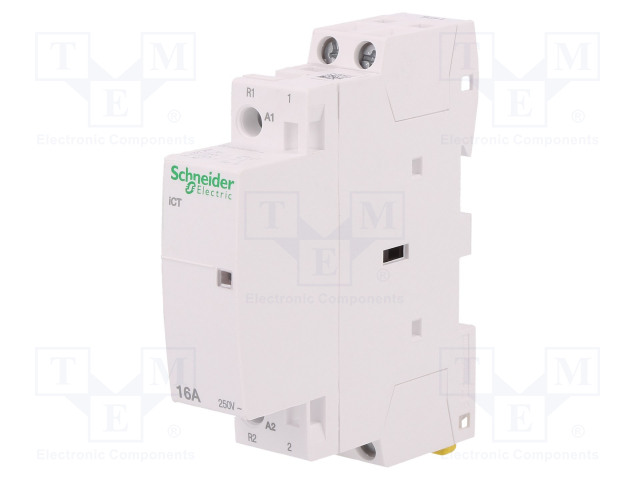
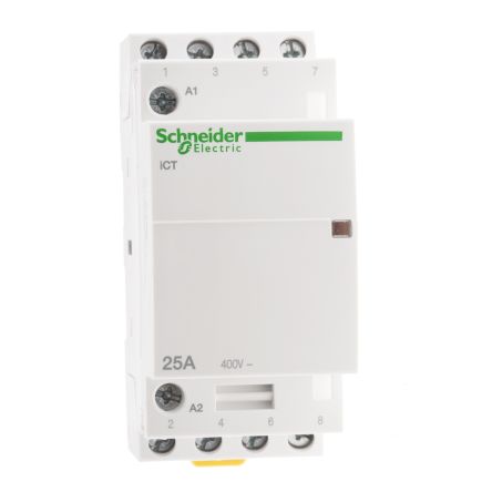
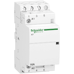
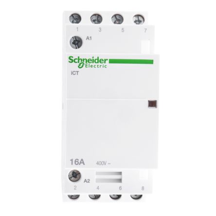
Tutorial 1 basic push start stop contactor kontrol kontaktor dengan push button start stop duration. Ict contactors can be combined with auxiliary control protection and indication functions.

Giving You Total Control Of Your Installation Manualzz
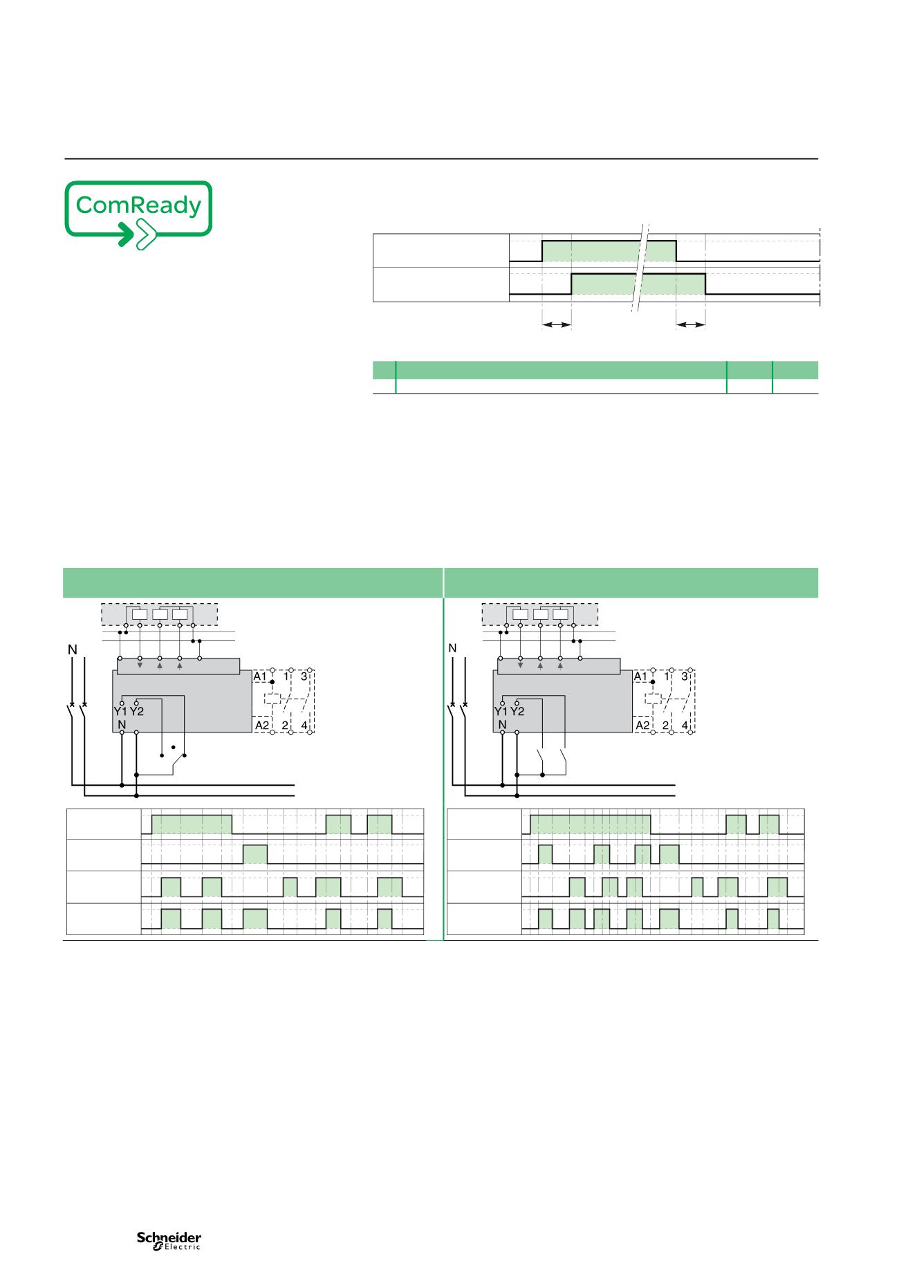
Schneider ict contactor wiring diagram. Wiring riddle no 3 auto transfer. The tesys k range contactors lc1k and tesys lr overloads lr2k have additional pins on their overloads to make direct connection to terminals 14 on contactor to 95 on overload and a2 on contactor to 96 on overload. Motor heating lighting javascript seems to be disabled in your browser. Magnetic contactor schneider electric tesys. Ict 16a 1no 24v 50hz contactor range. Contactor device short name.
Schneider electric contactor wiring diagram exactly whats wiring diagram. Contactor wiring diagram types of contactor electrical system buy contactor types of contactor contactor. Detail schneider contactor wiring diagram square d motor pdf. November 25 2018 by larry a. Wiring diagram book a1 15 b1 b2 16 18 b3 a2 b1 b3 15 supply voltage 16 18 l m h 2 levels b2 l1 f u 1 460 v f u 2 l2 l3 gnd h1 h3 h2 h4 f u 3 x1a f u 4 f u 5 x2a r. A wiring diagram is a type of schematic which uses abstract pictorial signs to reveal all the interconnections of components in a system.
The breadth of the ict contactor range satisfies most application cases. Binks channel 277032 views. Modular homes wiring diagram 4no electrical 4p 25a wct manual contactor buy wct manual contactor modular homes ict product on. Acti 9 product name. Wellborn assortment of schneider electric contactor wiring diagram. Ict device application.
Wiring diagrams 23 11 24 12 12 14 13 13 23 14 24 31 42 t x mounting b mounted to the right of ict b mounted to the left of ict by yellow clips 1. A wiring diagram is a streamlined conventional pictorial depiction of an electric circuit. Acti 9 ict product or component type. A9c20732 ict 25a 2no 230240v 50hz contactor. Browse our products in modular contactor for ict with exclusive features acti 9 ict din rail contactor is definitely geared to absolute safety. It shows the elements of the circuit as simplified shapes and also the power as well as signal connections between the devices.
These diagrams do not relate to such systems unless the 2 right hand pins are first removed.

