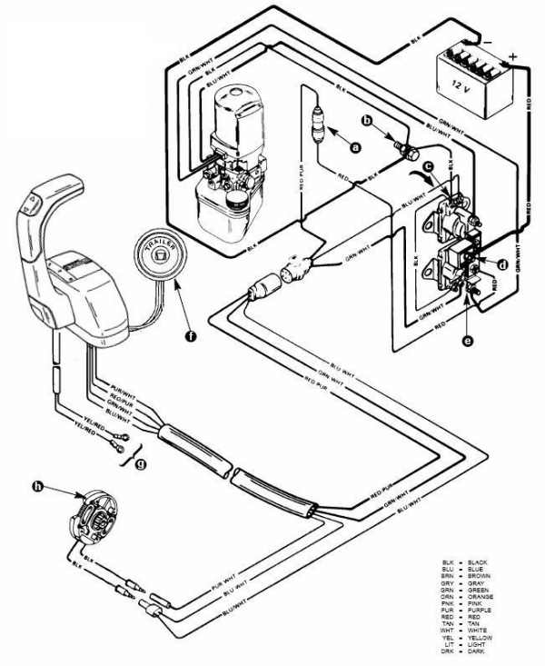
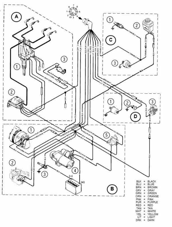
The marine mechanic im going to connect you with knows all the tricks and shortcuts. The wiring diagram illustrated on the back page represents a common installation and is not meant to be a guide for wiring a specific vessel.

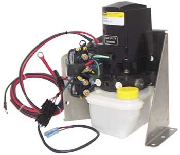
Gl 8918 Mercruiser Trim Pump Wiring Diagram Schematic Wiring
Sae j1171 marine wiring diagram. The marine sae j1171 testing procedure is as follows. When the red wire is connected the solenoid plunger should pull in and stay in until the either the red or black wire is disconnected. Ul 1500 and sae j1171 external ignition protection requirements rated ip67 temporary immersion for 30 minutes wire size and fuse rating chart awg charging amps minimum wire size fuse rating. See diagram c connect the black wire first followed by the white wire. Find sae j1171 marine trim pump service manual or just about any type of ebooks for any type of product. Sae j1171 marine trim pump service manual pdf best of all they are entirely free to find use and download so there is no cost or stress at all.
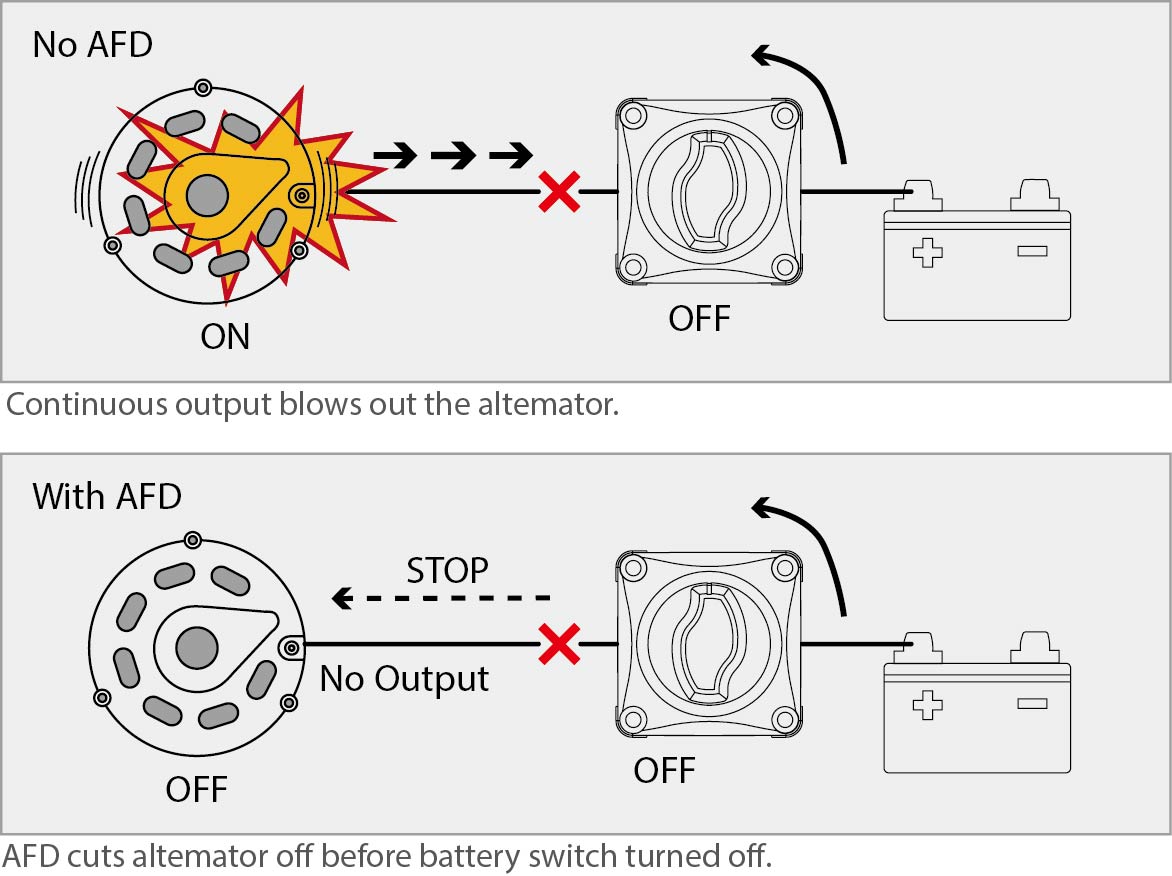
The alternator is then placed in an explosion proof test chamber. A sparking device similar to a spark plug is installed in the brush area of the alternator. A sparking device similar to a spark plug is installed in the brush area of the alternator. Another device is also installed in the brush area of the alternator to supply a specified mixture of propane gas and oxygen. The white and black wires should stay cool even after a few seconds have passed. I have marine sae j1171 and i need to know what three wires i need for im meter.
The alternator is then placed in an explosion proof test chamber. Test standards to determine ignition protection include sae j1171 external ignition protection of marine electrical devices and ul 1500 ignition protection test for marine products and the electrical system requirements for boats in title 33 cfr 183410a. The marine sae j1171 testing procedure is as follows. Sometimes boat issues seem like theyll be really complicated but end up being easy to fix. Another device is also installed in the brush area of the alternator to supply a specified mixture of pr opane gas and oxygen.


