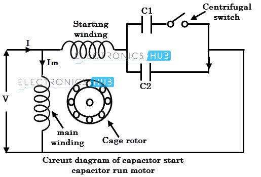
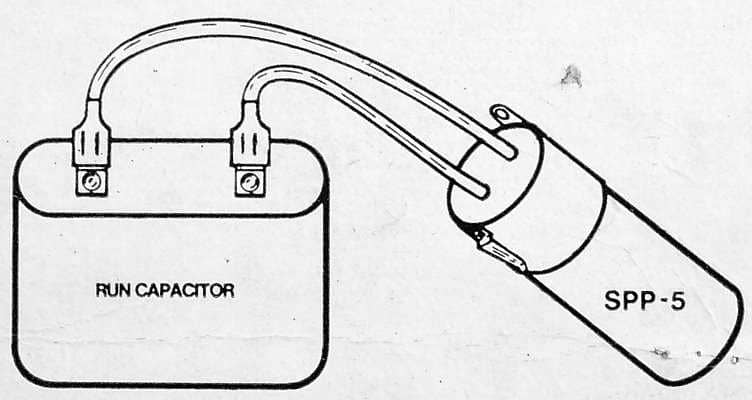
Each component should be placed and connected with other parts in particular manner. I think they were in parallel that is start with start and run with run.

Internal Wiring Configuration For Dual Voltage Dual Rotation
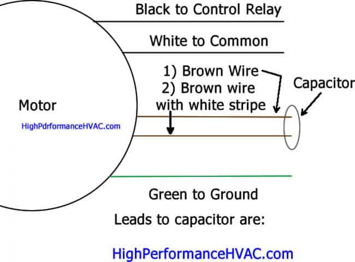
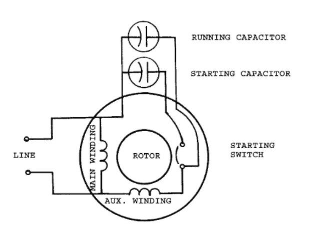
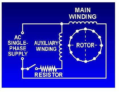
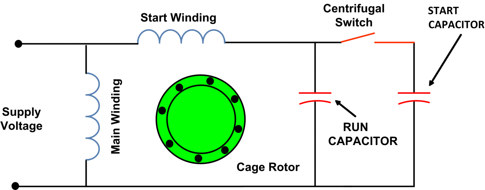
Run and start capacitor wiring diagram. Learn how a capacitor start induction run motor is capable of producing twice as much torque of a split phase motor. Single phase motor wiring diagram with capacitor start capacitor run. Click here to view a capacitor start motor circuit diagram for starting a single phase motor. It includes instructions and diagrams for various types of wiring methods and other items like lights home windows etc. Push the wire terminal on the start capacitors second wire onto the run capacitors common terminal often labeled c com the wire connected to the motors run terminal marked as r on the motors wiring chart and the wire going to the hot terminal on the load side of the contactor also connects to this run capacitor terminal. Motor run capacitor wiring diagram you will want a comprehensive professional and easy to comprehend wiring diagram.
Wondering how a capacitor can be used to start a single phase motor. If not the structure will not work as it should be. C common connector. S start wire connector. The relay is essex rbm c27b and the thermal switch is klixon type leh 33kb f2a. Also read about the speed torque characteristics of these motors along with its different types.
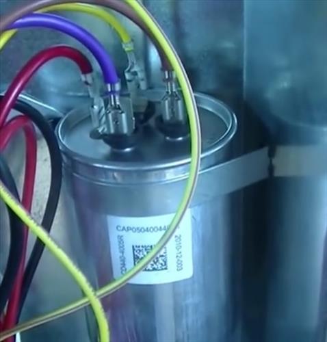
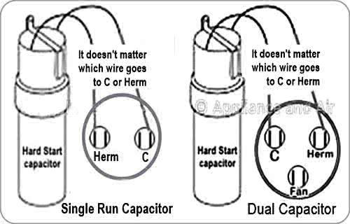
But replacing a start capacitor without first checking for shorted or open windings an open reset and a faulty centrifugal switch will not make your motor run if the capacitor is not really your problem. Motor run capacitor wiring diagram ac motor run capacitor wiring diagram capacitor start capacitor run motor wiring diagram pdf capacitor start induction run motor wiring diagram every electric structure is composed of various diverse pieces. Wiring diagram consists of many in depth illustrations that show the link of varied things. Two start and two run. With such an illustrative manual you are going to be able to troubleshoot avoid and full your assignments without difficulty. In our capacitor testing and wiring sketch at left you note we use the letters s c and r to identify the usual terminals to which a startrun capacitor is wired.
R run wire connector. L1 and l2 are designated as the two connection points representing the two electricity flow path inherent with single phase circuits where a single phase supply voltage is fed to the motors internal circuit. On many systems these terminals may be labeled so that the three leads on a startrun capacitor can be wired correctly. How to connect single phase single phase motor wiring diagram with capacitor. It is not uncommon for an electrolytic capacitor to dry out and fail in audio equipment after 20 years or less. There are four capacitors.
All off of the plate.
