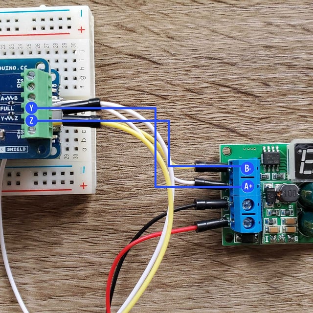
Several cables and wiring methods are referenced by installers when deploying modbus communications networks. Tighten the wire ties.
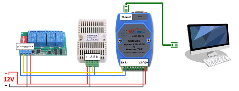
Ozeki Devices Masters Modbus Rtu Tcp Gateway Volison
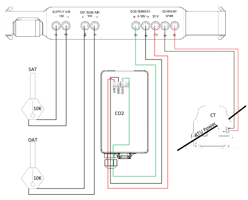
Rtu wiring diagram. A wiring diagram is a simplified standard pictorial depiction of an electrical circuit. Use the unit wiring diagram to make the low voltage connections. 1 mount the controller page 6. Route wires through loose wire ties provided in unit as in figure 1. Trane wiring diagrams simple xe air conditioner. Rtu open 5 to install the rtu open.
Official trane heat pump wiring diagrams block and schematic. Trane rooftop unit wiring diagram inspirational. Secure the ex cess wire bundle under the wire ties in the outdoor section do not leave excess wire in the electrical enclosure. Trane xr13 heat pump wiring diagram inside. Collection of york rooftop unit wiring diagram. Trane xl wiring diagram arcnx co.
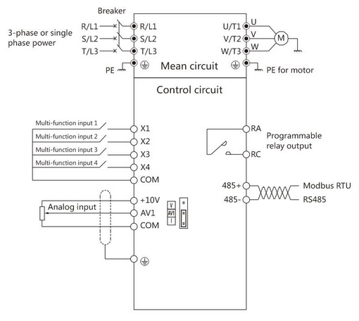
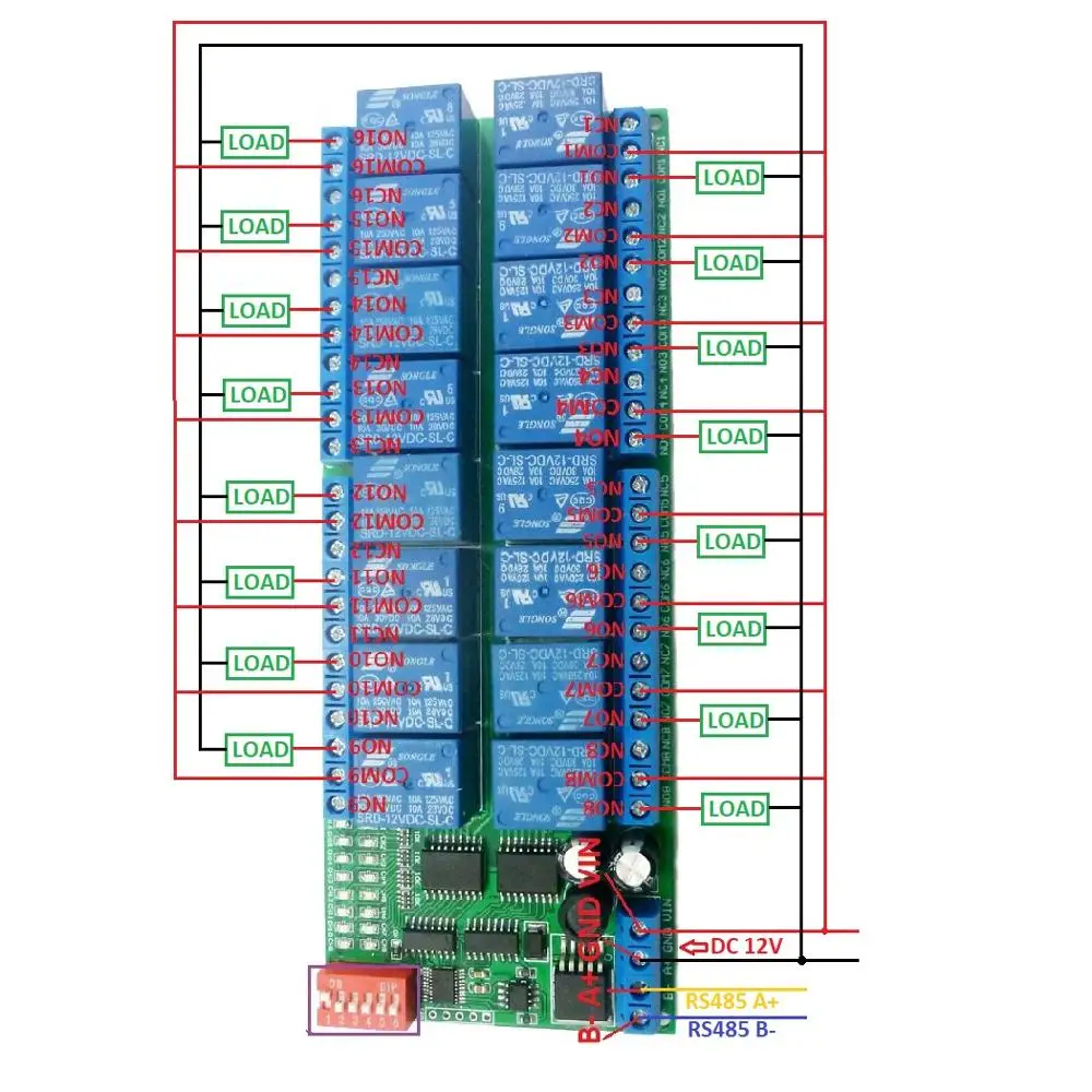
It reveals the parts of the circuit as streamlined forms and also the power and also signal links between the tools. Packaged rooftop units heat pumps outdoor air handling units installation operation maintenance o do not store gasoline or other flammable vapors and liquids in the vicinity of this or any other appliance o what to do if you smell gas. Cable termination rs485modbus rtu line bias overview. Disconnect electrical power to the rtu open before wiring it. Color coded wiring diagram. Jun 09 i badly need a refrigeration diagram of the trane voyager i rooftop unit.
Figure 2 fiycopo powered convenience outlet. Engineers at deck monitoring have reviewed information from many sources to create the following recommendations for a standard and robust wiring method. 2 wire the controller for power page 7. Trane rooftop unit wiring diagram trane voyager rooftop ac wiring diagrams wire center u2022 rh flrishfarm co 3 wire thermostat wiring diagram honeywell thermostat wiring diagram. Trane xr13 wiring diagram. Failure to follow this warning could cause electrical shock personal injury or damage to the controller.
Gallery of Rtu Wiring Diagram