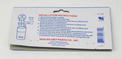
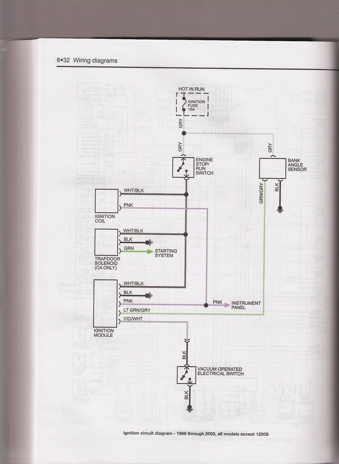
Examine the wiring diagram on the compressor unit. Rated for 112 hp to 15 hp compressors.

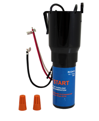
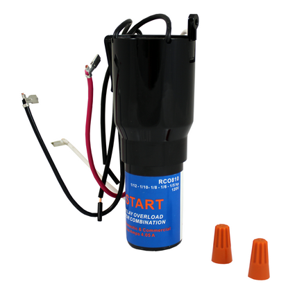
Rco810 3 In 1 Relay Combo Kit For Capillary Refrigeration Systems By Partsbroz 1 12 To 1 5 Hp Replaces Parts Numbers Tj90rco810 Ap4503019
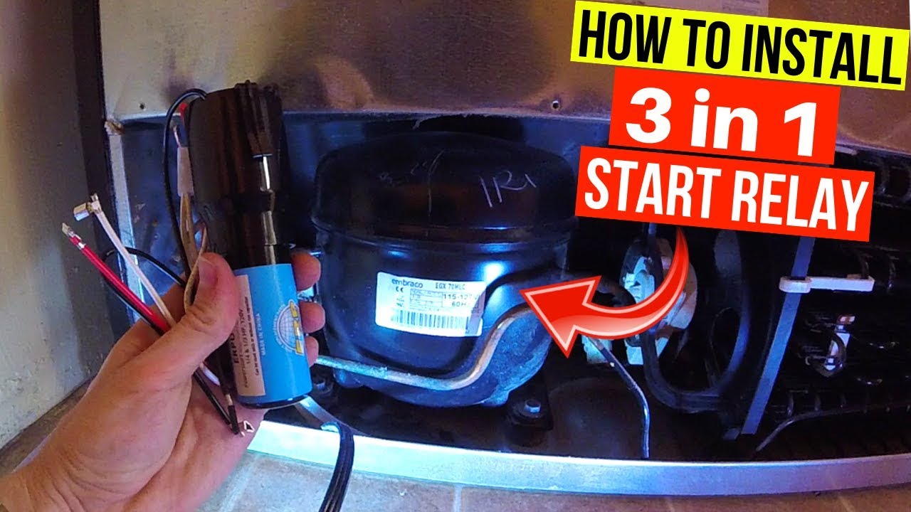
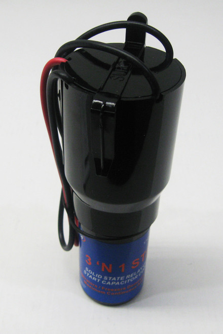
Rco810 wiring diagram. Used refrigeration systems with or without run capacitors. 110 to 125vac solid state hardstart relay includes relay overload and start capacitor. Used on refrigeration systems with or without run capacitors. Step 6 grasp the 3 n 1 relay box and locate the five wires protruding from it. A wiring diagram is a simplified conventional photographic depiction of an electric circuit. Relatively easy to install helps if you can read a circuit diagram as you will be replacing 3 discreet components with 1 plugging the 3 wires with connectors onto the compressor and connecting the other 2 wires via marettes twist on wire connectors to the ac feed wires that previously were connected to the relay and overload protector.
The diagram will display which terminals on the compressor have positive negative and neutral charges. These are a universal set of relays you can use in place of the factory relays installed on your compressor. 110 to 125vac solid state hardstart relay includes relay overload and start capacitor. There are three color coded wire plugs redpositive blacknegative and blueneutral to match the terminals. Variety of supco 3 in 1 wiring diagram. Maximum rla 405 amps.
It reveals the elements of the circuit as simplified shapes as well as the power and signal links between the devices. This is a video showing you how to install a 3 in 1 start relay. You would want to use. Prevents low voltage starting problems.
Gallery of Rco810 Wiring Diagram