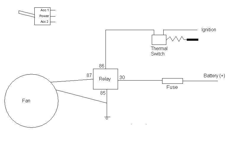
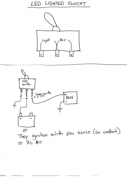
Step 1 wiring. Now take the power wire from your fan and connect it to the wire that is going through the firewall.

97civicex Radiator Fan Not Working Car Overheats Need Help
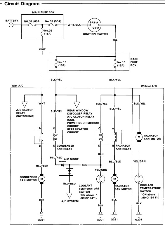
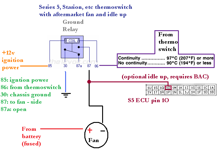
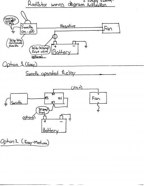
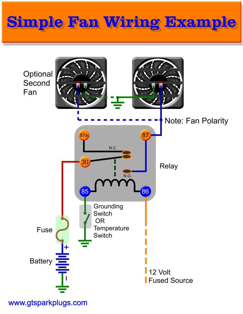
Radiator fan switch wiring diagram. Cooling fans are now controlled by the ecm through the respective module network and using duty cycle control signals. The color coded diagram below will correspond with the wires on the relay kit to help simplify the wiring process. This will be the wire that connects your switch to your fan power wire. You will then need switched power usually from your ignition switch wired to the blue wires on the relays. The first step in adding a switch to a radiator fan is to disconnect the batterys negative terminal. Get the 10 gauge wire and place it through the hole in your fire wall.
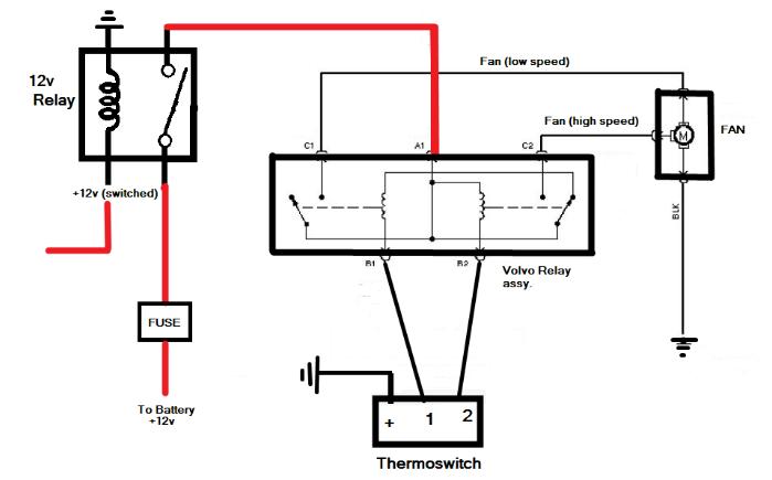
Suggested electric fan wiring diagrams converting a 12 volt switch into a ground switch these diagrams show the use of relays onoff sensors onoff switches and onoff fan controllers. Connecting a single cooling fan is a rather straightforward system it relies on a separate temperature sender to switch the fan on or you can utilize the cooling fan output if youve installed an aftermarket efi conversion. Start with taking both of the positive wires from the fans and run it to the yellow wires on each relay. Now find the wire that is connected to the motor of the electric fan. So now we have a wire that goes through the engine bay to the cabin of your car. Adjustable fan switch with radiator probe ground switching non variable speed only 30 40 amp fan 1 fan 2 hayden 3653 pn.
With the help of a wire cutter cut the wire at a distance of twelve inches from the start point. Here youll also be exposed to the current path voltage and sensor signal. In5408 make sure the diode band.


