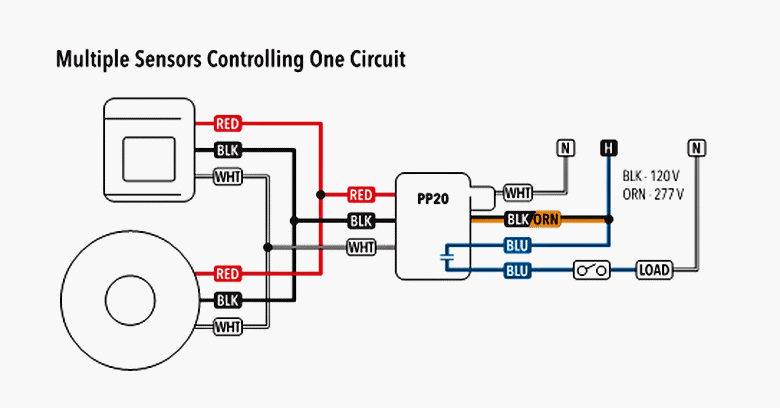
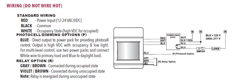
The pp20 transforms 120 240 or 277 volts to class ii 15 vdc to power the remote sensors. For 240 277 vac connect the orange to hot white to neutral and cap off the black wire.

0 10 V Lighting Control Wiring Diagram Dimmer Circuit Diagram
Pp20 wiring diagram. 60 hz switching load 120277 vac 2 pole independent switching see table for contact rating use 14 awg wire inputs diode pulse 18awg wire. For 120 vac connect the black wire to hot white wire to neutral and cap off the orange wire. Click add to cart to buy sensor switch pp20 power packalso known as. 2 pole 120277vac designed for use with diversa load occupancy sensors and diode pulse relays. 2 pole 120277 vac voltage 120277 vac. Lighting lighting controls occupancy sensors accessories power pack products related to pp20 power pack or visit the sensor switch site.
Pp20 power pack with 20 amp relay by sensor switch. For help with power pack from sensor switch. Utilizing our patented relay circuit protection the pp20 also switches the lighting load on and off. For 220 277 vac connect the orange to hot white to neutral and cap off the black wire. Wiring multiple power packs together typical wiring diagrams do not wire hot note. Wiring diagrams blk 120 v pp20 orn 277 v blk 120 v pp20 orn 277 v.
Power packs are the heart of the low voltage sensor system. For 120 vac connect the black wire to hot white wire to neutral and cap off the orange wire. Wiring multiple power packs together one sensor controlling two circuits standard wiring the power pack must be connected to a single phase hot and neutral system. 745975809592 nlight power pack sespp20 sensor switch pp20 accessories occupancy sensors lighting lighting controls. The power pack must be connected to a single phase hot and neutral system.
Gallery of Pp20 Wiring Diagram