Pnoz s41 operating manual pnoz s41 21890 en 07 12 when installed vertically. Secure the unit by using a fixing element eg.

Pnozsigma Safety Relay For E Stop Safety Gates Light
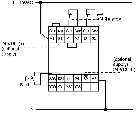
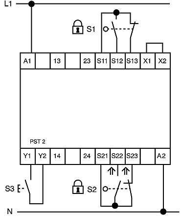
Pilz s4 wiring diagram. If there is a danger of exceeding the cable runs we recommend the. Pnoz s4 operating manual pnoz s4 21396en13 8 push the device upwards or downwards before lifting it from the din rail. Pilzgmbh at pilzde 2 function descriptionfunktioneneinkanalig single channel operation. Wiring important for detection of shorts across contacts. The pnoz s4 series from pilz are safety relays for monitoring e stop pushbuttons safety gates and light beam devices. Retaining bracket or end angle push the device upwards or downwards before lifting it from the din rail.
All rights to this documentation are reserved by pilz gmbh co. 49 711 3409 133 e mail. Operating manualen safety relays. Wiring please note information given in the technical details 19 must be followed. Wiring please note information given in the technical details 19 must be followed. The safety relay meets the requirements of en 60947 5 1 en 60204 1 and vde 0113 1 as safety component in accordance with the lift directive 9516ec and en 81 1.
The safety relays pnoz s1 and pnoz s2 are suitable for monitoring e stop and safety gatesthe devices pnoz s3 pnoz s4 and pnoz s41 can also be used to monitor e stop and safety gates their area of application also includes monitoring of light guards. Pilz pnoz s4 wiring diagram awful pilz pnoz s4 wiring diagram pilz pnoz s3 free wiring. As this function for detecting shorts across contacts is not failsafe it is tested by pilz during the final control check. Pnoz s4 pilz gmbh co. In the application at plants and machines one pnozsimga safety relay is used per safety function. As this function for detecting shorts across contacts is not failsafe it is tested by pilz during the final control check.
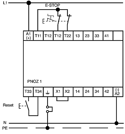
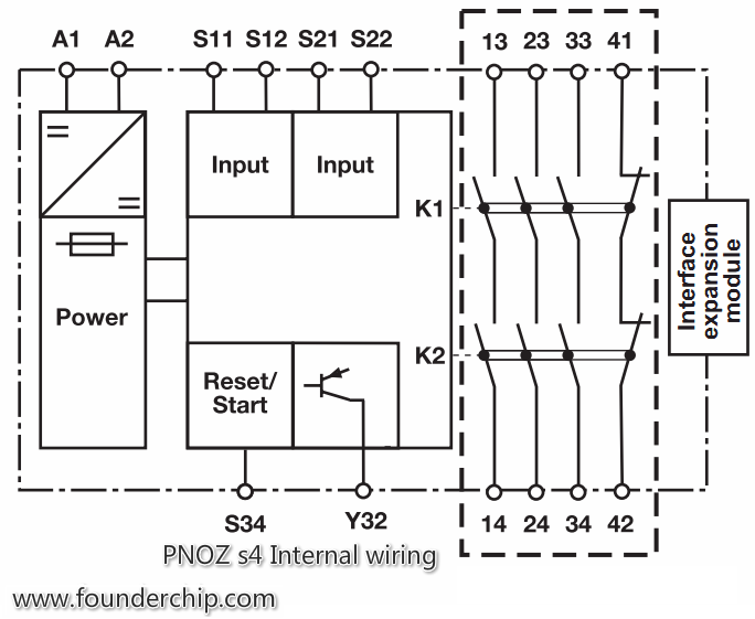
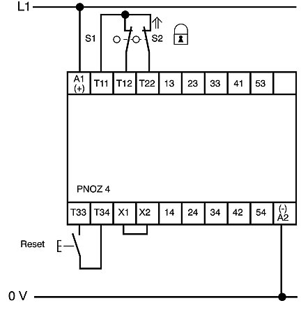
Ensure the wiring and emc requirements of iec 60204 1 are met. No re dundancy in the input circuit earth faults in the reset and input circuit are detected. Output 4142 is an auxiliary contact. Important for detection of shorts across contacts. It shows the components of the circuit as simplified shapes and the talent and signal contacts between the devices. Wiring please note information given in the technical details must be followed outputs 1314 2324 3334 are safety contacts.
Secure the unit by using a fixing element eg. This document is the original document. Kg felix wankel straße 2 73760 ostfildern germany 1001742 en 05 2012 03 telephone. 49 711 3409 0 telefax. Pnoz s4 wiring diagram wiring diagram is a simplified gratifying pictorial representation of an electrical circuit. Retaining bracket or end angle push the device upwards or downwards before lifting it from the din rail.
Pnoz s4 operating manual pnoz s4 21396 en 15 12 when installed vertically. If there is a danger of exceeding the cable runs we recommend the following test after the installation of the device.

