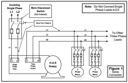
Resistive or single phase loads andor magnetic switch gear. Find the model on the chart that correlates to the total system horse power and largest motor.

Monthly Meeting April 22 2006
Phase o matic wiring diagram. It shows the components of the circuit as simplified shapes and the power as well as signal links in between the devices. Wire the phase a matic static phase converter to the idler motor as described in method no. The sideway diagram as shown here is to suit the illustration space only. Work out the size you need. Mount converter upright with the junction box on the top. E suite 301 palmdale ca.
Mount converter upright with the junction box on the top. The sideways diagram as shown here is to suit the illustration space only. Phase a matic static phase converter installation regarding 3 phase converter wiring diagram by admin from the thousands of photographs on the net in relation to 3 phase converter wiring diagram we all picks the best choices along with best quality exclusively for you all and now this photographs is usually one among photographs choices in our ideal pictures gallery about 3 phase converter. Estimate the size you need by following these three easy steps. Size fuses and wires on the 3 phase side as appropriate for the motors rated amperage. List all motors on the system by size and type of use.
March 27 2019 by larry a. Add up the horse power rating of each motor to get the total system horse power. To the idler motor as per method no. Assortment of phase o matic wiring diagram. A wiring diagram is a simplified standard photographic representation of an electrical circuit.
Gallery of Phase O Matic Wiring Diagram