I drive this occurs when the controller detects that the battery voltage has. 44 0 1425 271444.
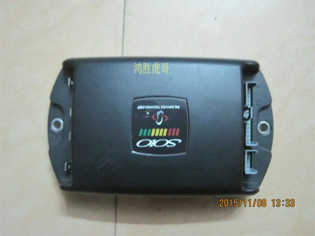
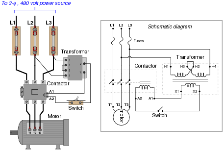
Pg Drives Technology S Drive Wiring Diagram General Wiring
Pg drives technology i drive wiring diagram. Pg drives technology s drive wiring diagram. Check all the connections and leads between the motor and the i drive. Except as permitted by such terms no part of this manual may be reproduced stored in a retrieval system or transmitted in any form or by any means electronic mechanical recording or otherwise without the prior written permission of pg drives technology. The output current ratings and restrictions the connector pin assignments recommendations for the cross sectional area ratings and materials for wiring are given in the table in section 42. If the trip is still present after the potentiometer connectors and wiring have been checked the controller may be. The motor has a bad connection.
Freewheel switch trip the freewheel switch is activated or the manual brake disengagement mechanism is operated. The i drive is one of the most advanced and cost effective digital controllers available to date and has been designed specifically for applications such as walk behind floorcare machines and small materials handling devices. Connections and relevant wiring to the controller. 2 i drives technology hapter nstallation wiring general study the data sheet for the control system to identify. View products service center history. Pg drives technology formerly known as penny giles drives technology began designing manufacturing and marketing sophisticated motor speed controllers in 1976 and the company became established as the worlds foremost supplier of such products for mobility vehiclesin addition to leading this market sector pg drives technology became a.
Pg drives technology accepts no liability for any losses of any kind if the points are not followed. Check the position of the freewheel switch. Motor wiring trip the motor has a short circuit to a battery. Check the position of the switch or lever and all connections between the switch and the s drive. This is because the control system is able to detect problems in other electrical components motors batteries solenoid brakes etc or more importantly the wiring to them. Construed as a commitment by pg drives technology.
Pg drives technology accepts no liability for losses of any kind arising from an incorrect or. Check all the connections and leads between the motor and the battery. The electronics of the i drive controller are sealed against water ingress to ipx5 and when the optional connector sealing system is fitted the cable connections are. Microcontroller based electrical parameter monitoring system check all the connections and leads between the motor and the battery. Pg drives technology s drive wiring diagram also. Motor wiring trip the motor has a short circuit to a battery.
Check all the connections and leads between the motor and the battery. 8 vr2 technical manual sk77898 8 curtiss wright pg drives technology about this manual the technical manual gives an introduction to the vr2 control system. Inhibit active the i drive is being inhibited. When a control system has detected a trip a system trip is indicated.
Gallery of Pg Drives Technology I Drive Wiring Diagram