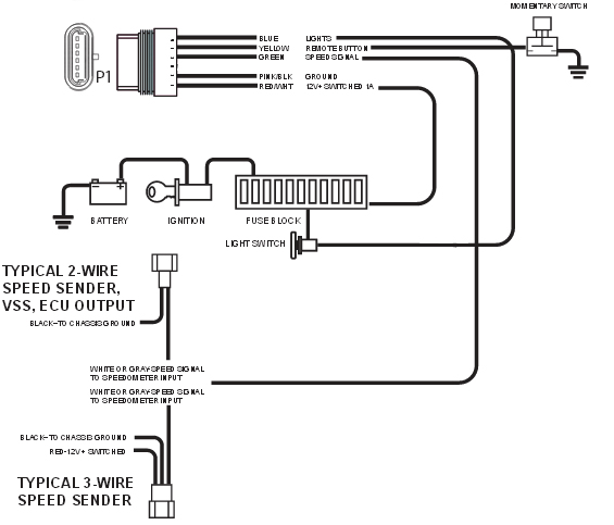
The omega digital vss has a red a black and a white wire. 10142009 122742 am.

32 Best Glowshift S Black 7 Color Series Gauges Images
Omega kustom gauges wiring diagram. A wiring diagram is a simplified traditional pictorial depiction of an electric circuit. Rebecca doremus created date. Compatible with all known computers including ls1 lt1 and all fords omega gauges are proudly made in the usa. All of omega kustoms instruments have the finest movements available today and the latest lighting technology. Omega gauges wiring diagram a novice s overview of circuit diagrams. Wellborn variety of omega gauges wiring diagram.
Omega kustom gauges 3 38 nd 4 38 speedee sensitivity. When you want the best in american made gauges look no further than. Tachometers are sold separately in both a 5 3 38 size and we also carry 2 116 12 volt quartz clocks 2 116 5 6 gauge sets. Literally a circuit is the path that enables power to flow. Omega kustom manual finalcdr author. The red wire is for the voltage input either from terminal a of the.
Omega kustom instruments manufactures high quality gauges using the latest technology. Omega kustom gauges wiring diagram wiring diagram is a simplified all right pictorial representation of an electrical circuit. A very first appearance at a circuit representation might be complicated but if you can check out a subway map you can review schematics. A wiring diagram is a simplified standard pictorial depiction of an electrical circuit. Darrian continues to explain how to calibrate the omega kustom gauges. July 4 2018 by larry a.
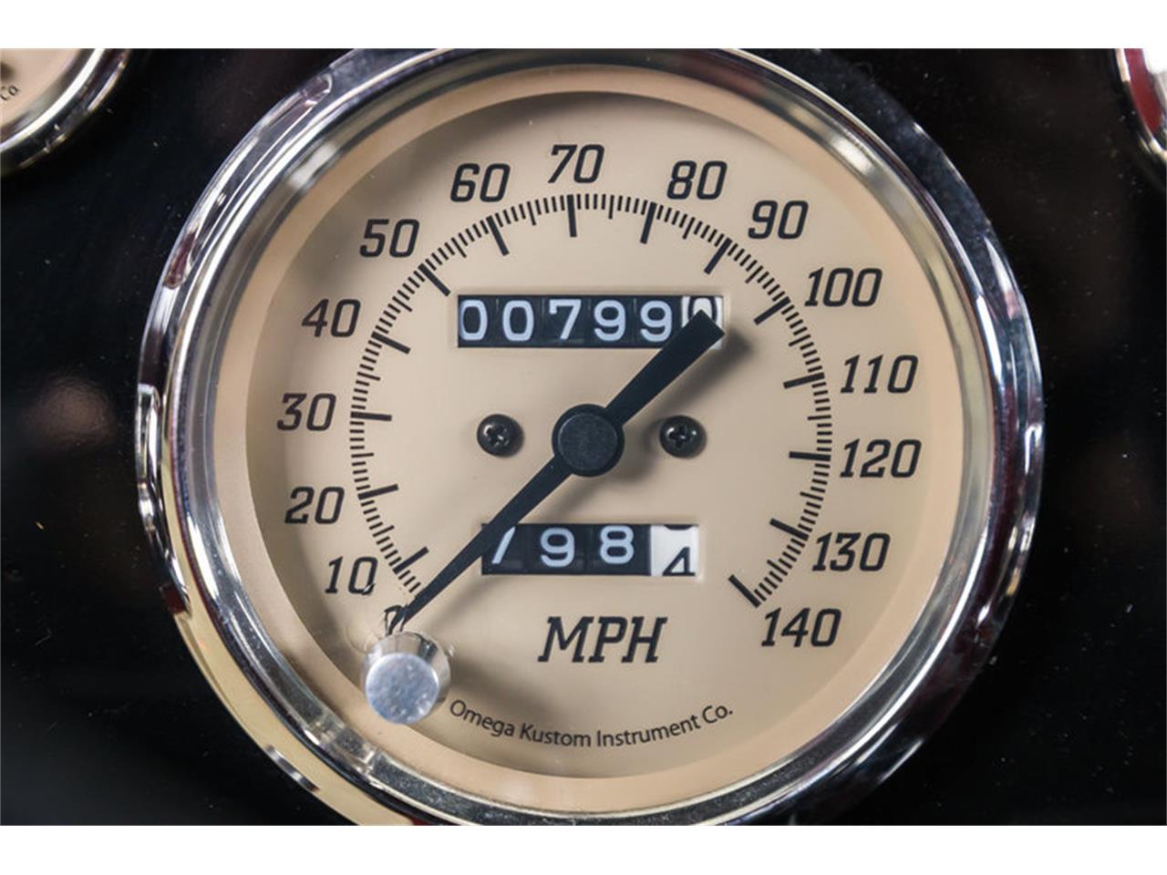
The function is the very same. Assortment of omega gauges wiring diagram. In the third and final instructional video on the omega kustom gauges darrian explains how to program the 3 n 1 omega gauge. Obtaining from point a to point b. Omega gauges feature polished stainless steel bezels and a real glass lens. It shows the components of the circuit as streamlined forms as well as the power and also signal connections in between the devices.
A negativeground potential and connect terminal b to the sensor signal wire. Here he will explain how to set up the b style gauge using a signal generator. It shows the components of the circuit as streamlined forms and the power as well as signal connections in between the devices. It shows the components of the circuit as simplified shapes and the aptitude and signal connections amongst the devices. Read the sensitivity description on page one to determine the necessity of.


.jpg)
