The osp power packs can also supply power to the osa20 add a relay. Heavy duty universal voltage power packs.

Power Packs Sensorworx
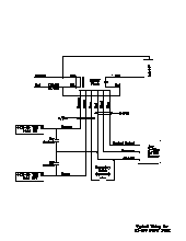
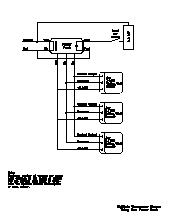
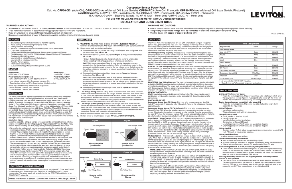
Occupancy sensor power pack wiring diagram. Multiple occupancy sensors can be connected to a single power pack in order to fully cover an area. Wellborn collection of occupancy sensor power pack wiring diagram. 20a 2400w at 120v incandescent 20a 2400va at 120v fluorescent 20a 5540va at 277v fluorescent 16a 4430va at 277v electronic ballasts 12 hp at 120v motor load 2 hp at 240. Opp20 0d1 auto on opp20 0d2 automanual on local switch opp20 rd3 auto on photocell opp20 rd4 automanual on local switch photocell load ratings. Lighting load 120 277 v 5060 hz pp dv upp dv 347 v 60 hz. The los c series ceiling mount occupancy sensors offer a wide range of technologies and can either integrate into lutron systems no power pack needed or function as a stand alone control using a lutron power pack.
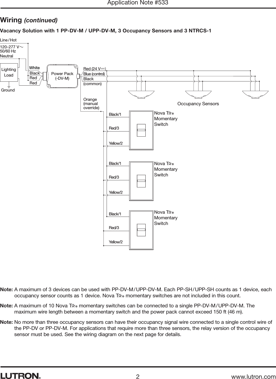
The relay in the power pack is controlled by the occupancy sensors connected. Connect the low voltage. It reveals the components of the circuit as simplified forms and the power and signal connections in between the devices. The primary power pack is the power pack switching the load. Assortment of lutron occupancy sensor wiring diagram. When using more sensors than this multiple power packs are required.
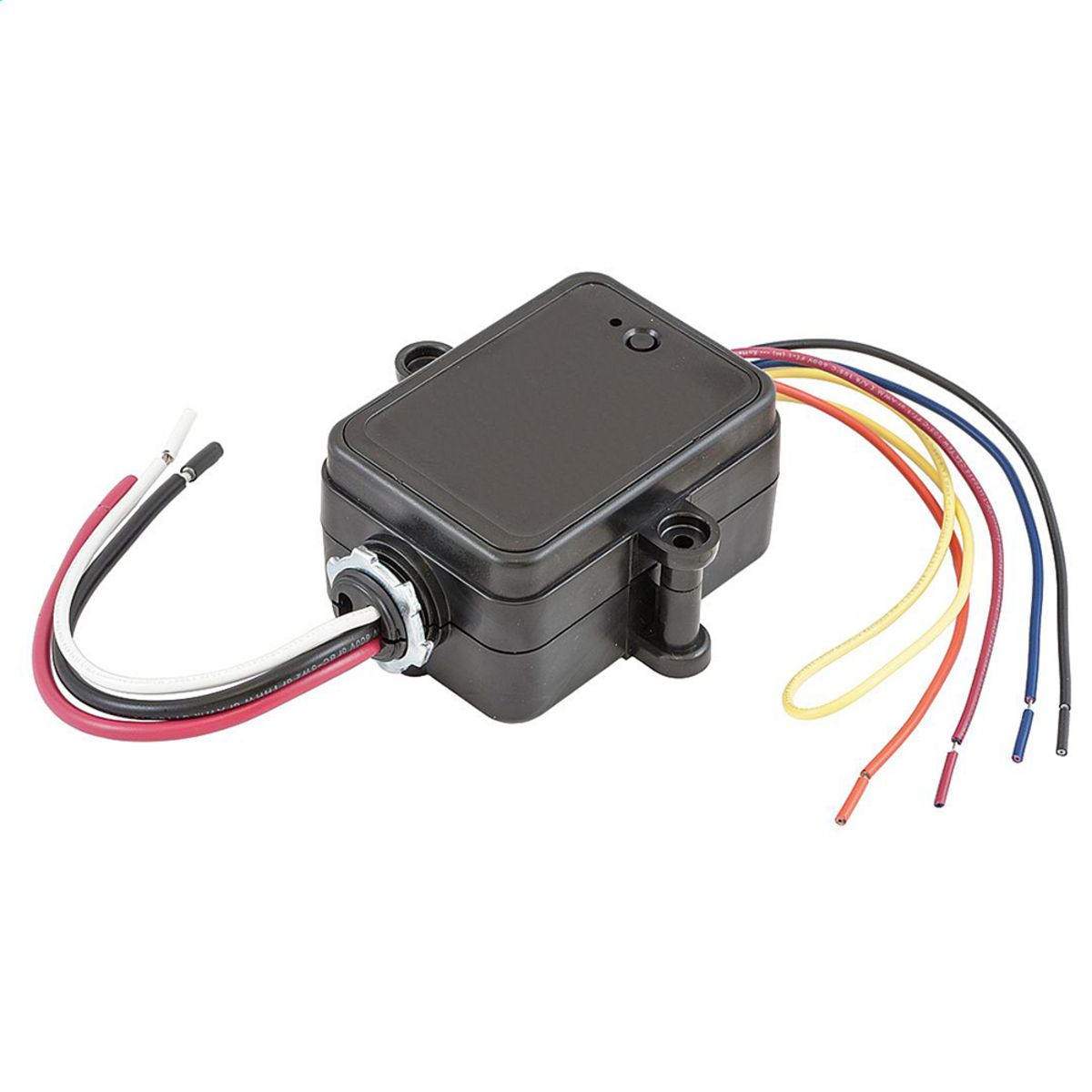
A wiring diagram is a simplified conventional photographic depiction of an electric circuit. The secondary power packs only provide low voltage power to the occupancy sensors. Red wire 24vdc from power pack to the 24v terminal on the sensor. It shows the components of the circuit as simplified shapes and the capability and signal connections amongst the devices. Occupancy sensor power pack cat. Occupancy sensors wiring 3 sensors with power pack pp dv upp dv or pp 347h 1 1 maximum 3 occupancy sensors can be used with pp dv upp dv or pp 347h.
Wiring diagram july 24 2019 2317. August 19 2018 by larry a. Refer to the wiring diagram on the next page for the following procedures. Occupancy sensor power pack wiring diagram hubbell motion sensor wiring diagram wiring diagram autovehicle. 2 when lights are manually turned off switch must be returned back to the on position for occupancy sensors to function as set. The power pack contains a power supply and a load switching latching relay.
The opp power packs can also supply power to the osa20 add a relay. It shows the parts of the circuit as streamlined forms and the power and also signal links in between the tools. Black wire return from power pack to common terminal on the sensor. A wiring diagram is a simplified standard photographic representation of an electric circuit. Connect as many sensors to the primary power pack as possible see current capacity section below by connecting the red wires of the sensors to the red wire 24vdc of the primary power pack. Instruction sheets specification sheets wiring diagrams.
The power supply provides class 2 low voltage power for oscxx oswxx and osfhp series occupancy sensors. Occupancy sensor power pack wiring diagram wiring diagram is a simplified usual pictorial representation of an electrical circuit. The relay in the power pack is controlled by the occupancy sensors connected via the 22 gauge blue occupancy wire.
Gallery of Occupancy Sensor Power Pack Wiring Diagram