Sensor the exhaust gas temperature egt sensors are inserted into the exhaust system just in front of the diesel oxidation catalyst doc sensor 1 and immediately before and just after the diesel particulate filter dpf sensors 2 and 3. Knock sensor location diagram if drive around with the check engine light on when a code p0332 or a p0327 is set in the computer memory engine damage could occur.

Isx15 E5 4954042 Wiring Diagram Rev 4 Throttle Diesel Engine
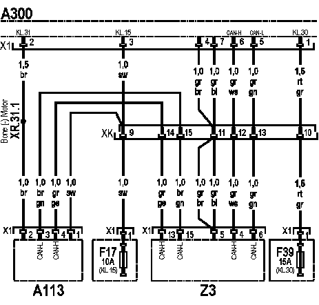
Nox sensor wiring diagram. If test of power supply confirms presence of necessary voltage connection of can should be performed. Wiring diagram index name description page aa power distribution frc 3 ab power distribution frc 4 ac power supply circuit protection 34 ef 5 ad power supply circuit protection 44 ef 6 ae grounding 7 af starting and charging 8. Installation of the nox sensor in the lupo fsi exhaust system source. Mercedes benz w210 wiring diagrams 1995 2001 w210 starter and generator engines 104 111 604 605 606 wiring diagram w210 speed signal of the front axle ges engines 104 111 602 604 605 606 schematics. These sensors produce an electronic signal based on temperature. Discussion starter 1 jan 31 2010.
Jump to latest follow 1 15 of 15 posts. The nox sensor as mentioned before is sold as a stand alone unit with the control box attached to the sensor. The nox sensor can be seen on the right hand side downstream of the nox adsorber. Thats the only valve you are going to get for troubleshooting the nox sensor. Sensor module then you may purchase the nox sensor module kit without the included sensor module. Should read battery voltage.
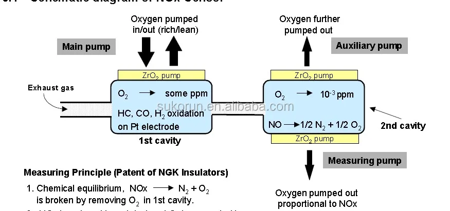
Please contact drivven for a quote. The first nox sensor by ntk and its evaluation electronics figure 6 shows a schematic of the exhaust aftertreatment system in the vw lupo 14 fsi. This sensor is also called the uni nox sensor by v d o for european cars. Labrat116 go steelers. What is the wiring differences between the 99 01 1wire knock sensor and the 2wire 02 07. Joined sep 6 2003 347 posts.
1 wire and 2 wire knock sensor wiring diagram. If 2eae re appears after nox sensor replacement f06 is blown repeatedly check wireset and all modules connected to this power wire. The wiring harness that is included with the usb nox kit is a five foot cable that connects to the nox sensor control module and then splits into two cables for the usb 8473 module and an external power supply. Measure the voltage between the aftertreatment outlet nox sensor battery voltage supply circuit and the aftertreatment outlet nox sensor return circuit at the nox sensor wiring harness connector. To me the most interesting part about the knock sensor is that it only has one wire going to it. The signals are sent to the engine control.
Gallery of Nox Sensor Wiring Diagram