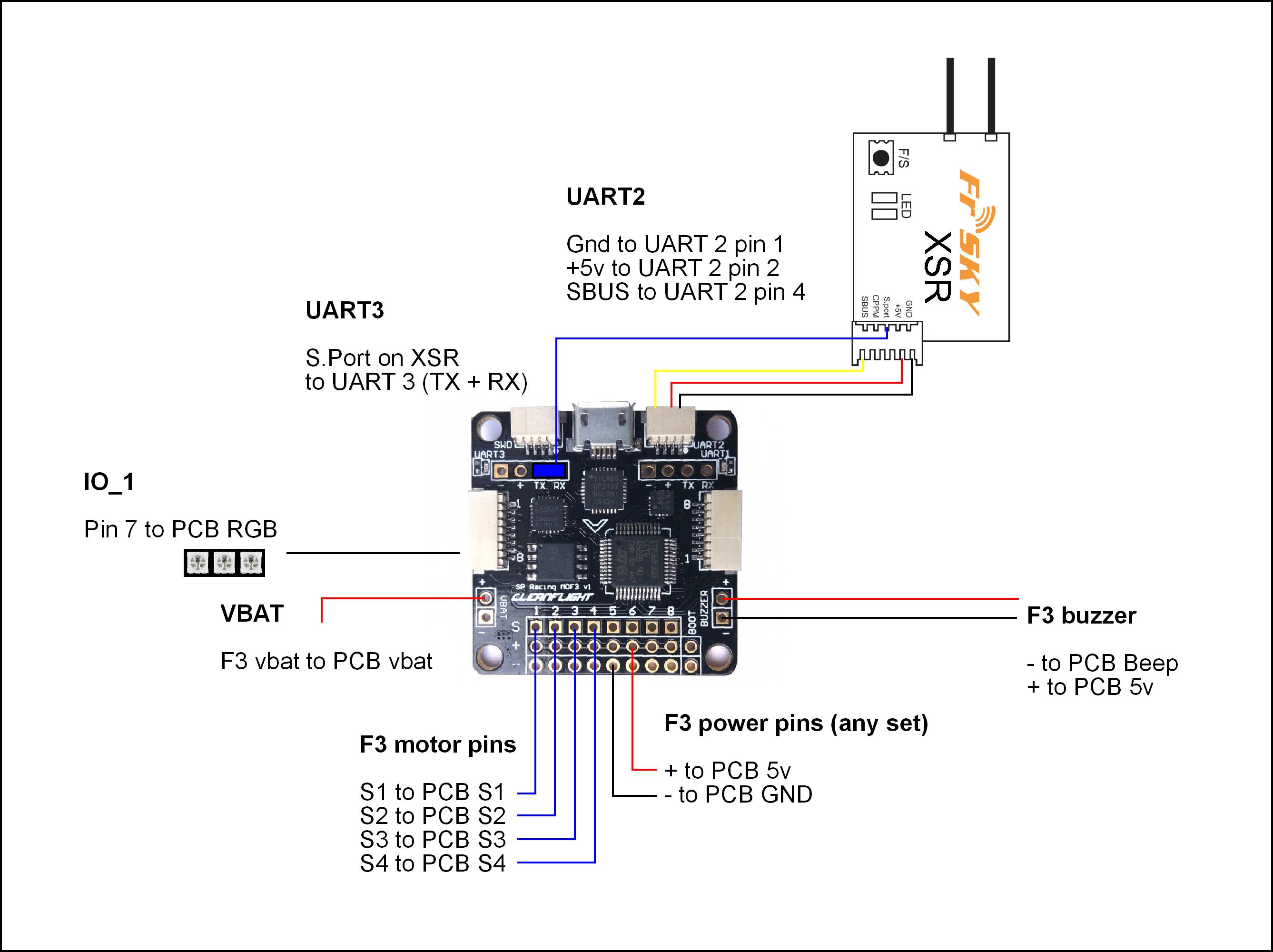
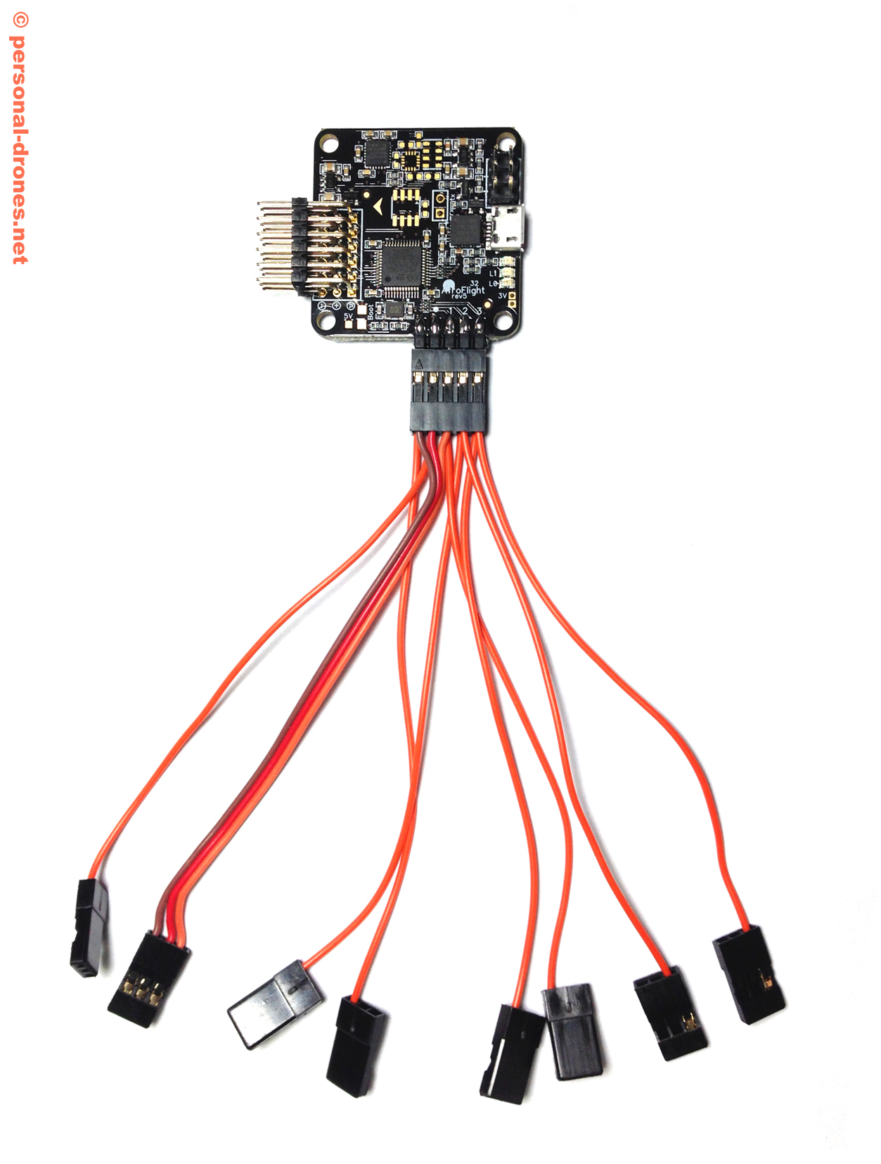
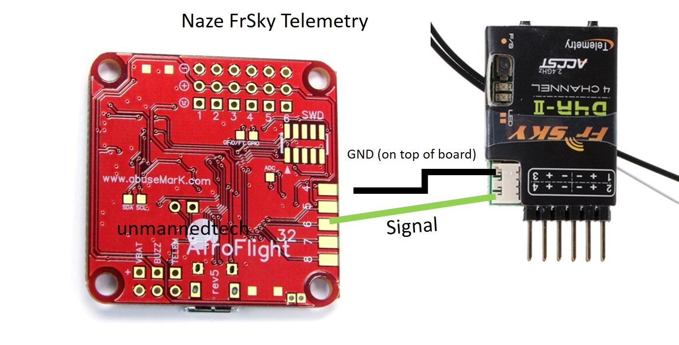
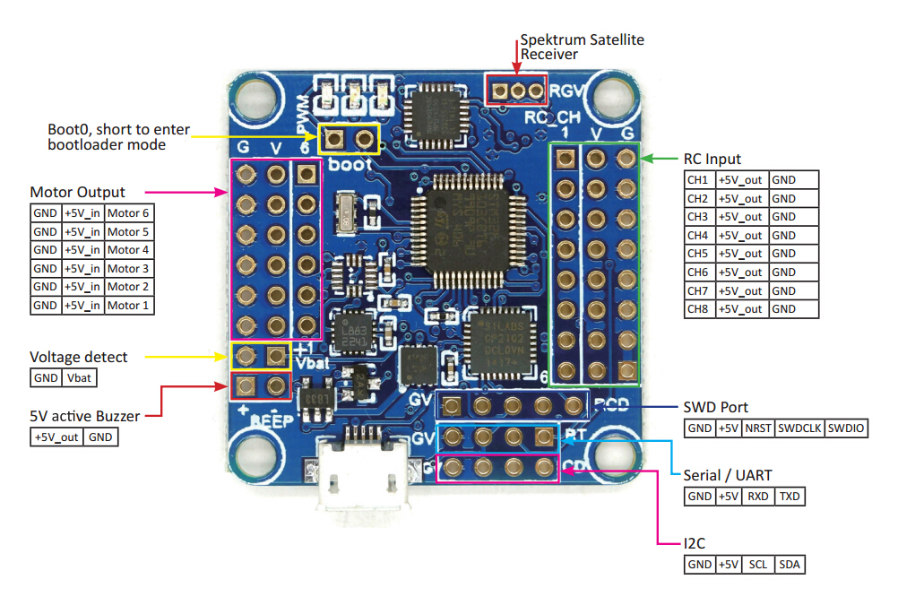
Connect all of the components as in the diagram below. 48 naze32 flight controller adding sonar hc sr04 module.

Naze32 Setup Guide For 250 Sized Quadcopters
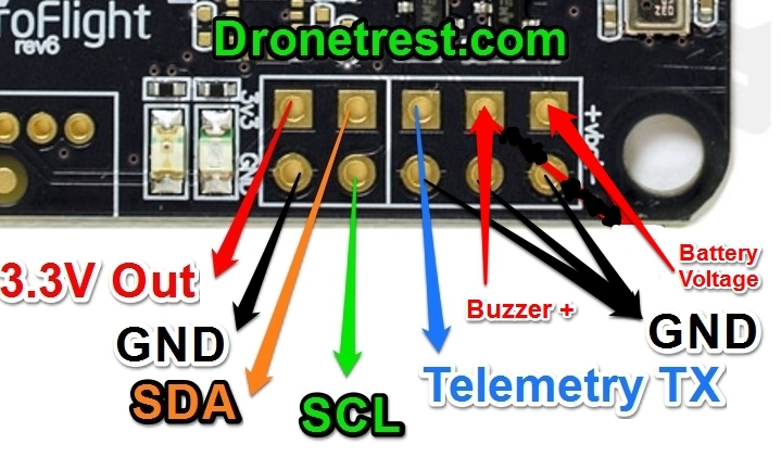
Naze32 wiring diagram. So depending on what receiver option you go with make sure you wire it as needed. Solder motor leads i routed mine underneath the board and i used a 3 pin and a single pin wire connector to. Refer to the diagram in figfull naze32 rev. 5 the naze32 is a stm32 based flight controller created by timecop. Connect all of the components as in the diagram below. Naze32 wiring diagram for dsm2.
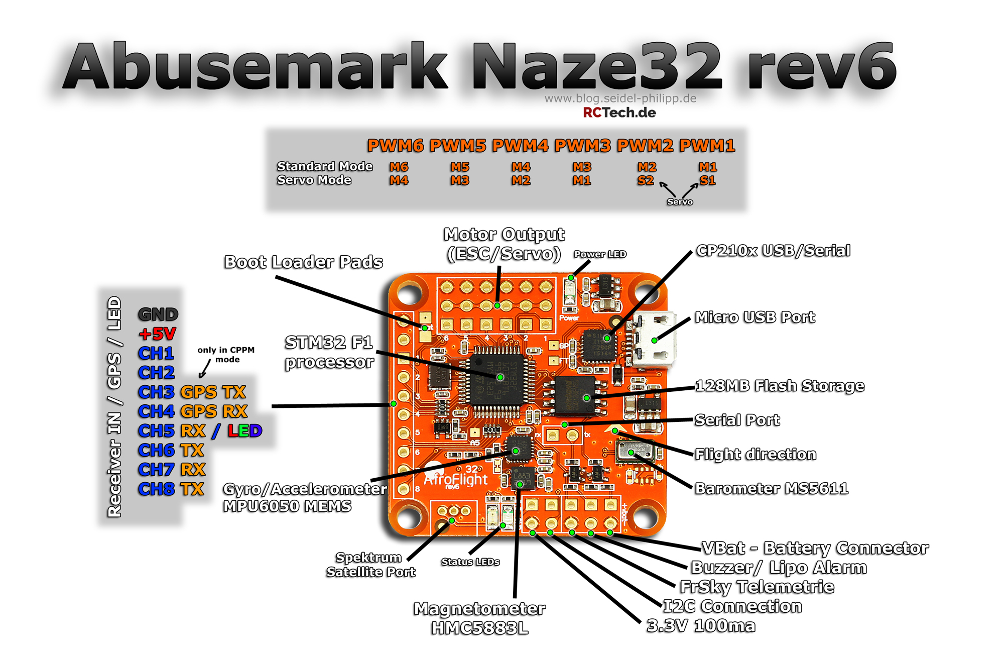
Aug 09 acro naze32 wiring diagram part 2 naze32 rev6 wiring zmr quadcopter build now onto the naze32 rev6 acro funfly flight controller configuration i have made a naze32 rev6 wiring diagram that you can follow on your quad build. Sometimes wiring diagram may also refer to the architectural wiring program. The stock firmware is a port of multiwii called baseflight which has several forks. Naze32 setup guide with wiring and baseflight settings for 250 quadcopter with cppm the following is a naze32 setup guide for use on a 250 quadcopter with a cppm receiver. The clockwise rotating escshow to connect components may these quadcopter wiring diagram guide help you making a few of your own drone a bit easier. Acro naze32 rev 5 basic guide some users in the rcgroups forum afroflight naze32 setup guide for dummies.
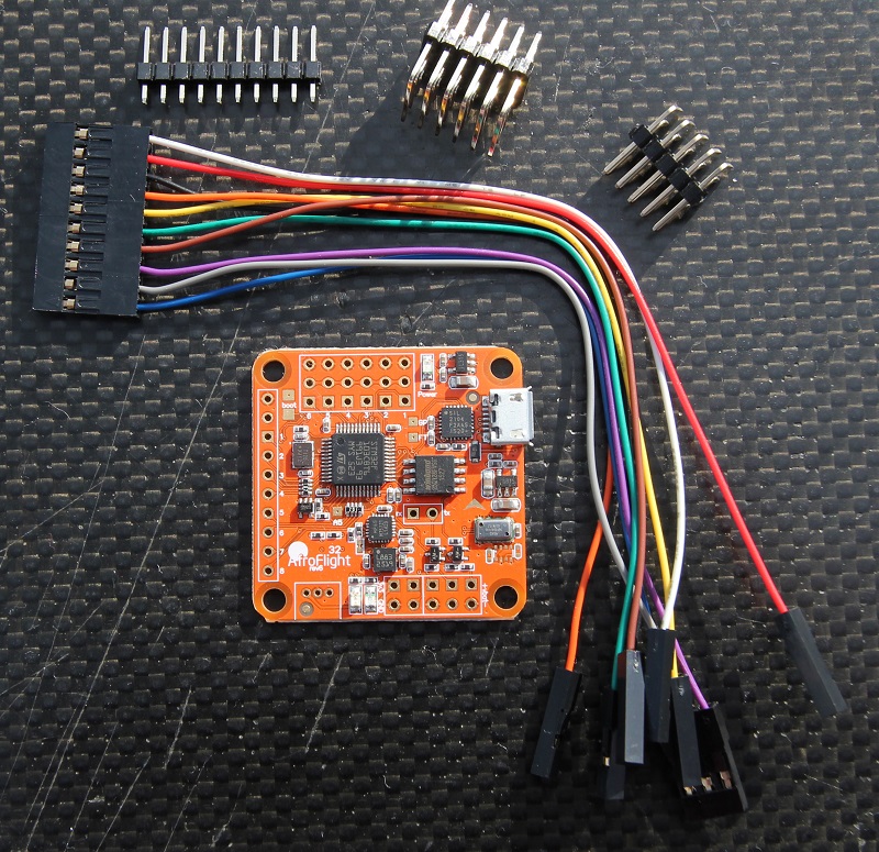
On typical naze32 connection diagram if i am not mistaken the esc to motor connections wiring are wrong. Naze32 setup guide with wiring and baseflight settings for quadcopter with cppm the following is a naze32 setup guide for use on a quadcopter with a cppm receiver. Part 2 naze32 rev6 wiring now onto the naze32 rev6 acro funfly flight controller wiring configuration. Zmr250 v2 naze32 rev6 wiring diagram. Naze32 rev6 wiring diagram 13122018 13122018 1 comments on naze32 rev6 wiring diagram the naze 32 rev 6 board has made some nice layout revisions such diagram if i am not mistaken the esc to motor connections wiring are. I chose to get an frsky x4r sbus receiver so i pulled the yellow wire from the wire pin connector you see below and soldered that to u2rx4 instead of running ppm as i originally thought i was.
The simplest approach to read a home wiring diagram is to begin at the source or the major power supply. It is 5 on page 11 of timecops manualdiagram wiring naze32 rev. The wiring diagram on the opposite hand is particularly beneficial to an outside electrician. 1 flight controller naze32 connection diagram.


