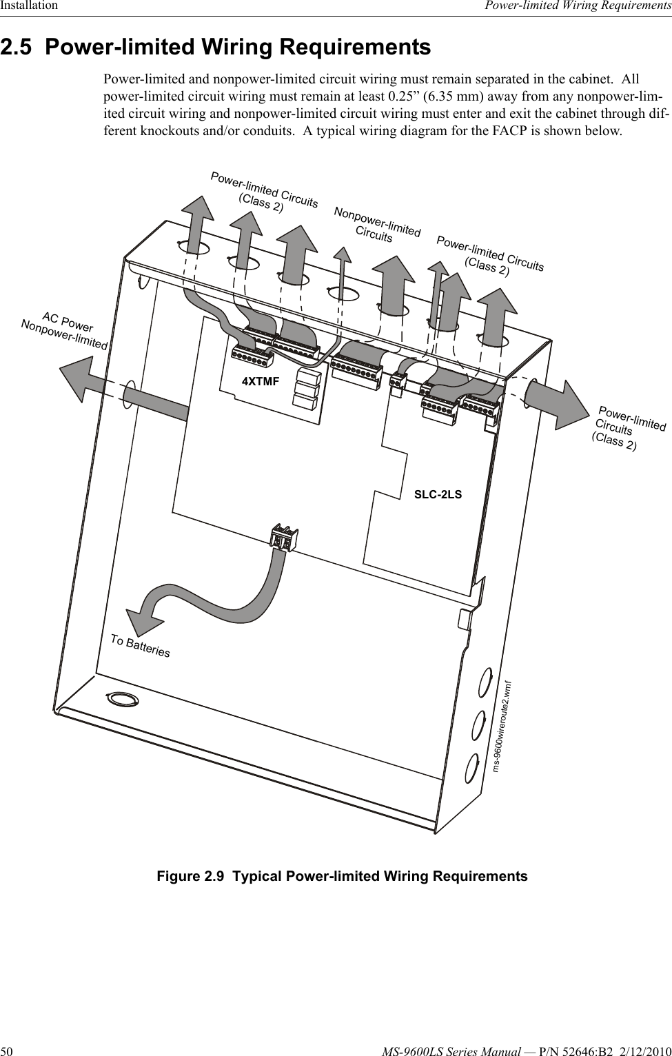
All wiring must conform to applicable local codes ordinances and regulations. They may also be mounted to the smb500 sur face mount box.
Notifier Control Module Wiring Diagram Notifier Fcm 1 Wiring
Mmf 300 wiring diagram. Refer to setting an slc address for a single point module on page 34. This module is intended for power limited wirin g only. Each module takes one address on the slc. K pn 51309k ecn 08 118. Led flashes during normal operation and latches on steady to indicate alarm. 01 159 on ms 9600 series panels 01 99 on other compatible systems.
Mmf 300 wiring diagrams 533 mmf 300 wiring for emergency alarm system applications connect the slc wiring to the module terminals 1 and 2. Sems screws with clamping plates for ease of wiring. Surface mounted electrical boxes smb500 are available. This module is intended for power limited wirin g only. The mmf 302 mounts directly to 4 square electrical boxes see figure 2a. All wiring must conform to applicable local codes ordinances and regulations.
The mmf 300 mounts directly to 4 square electrical boxes see figure 2. Sems screws with clamping plates for ease of wiring. Direct dial entry of address. Wiring a nfpa style d idc with an mmf 300. All wiring must conform to applicable local codes ordinances and regulations. The mmf 300 monitor module is intended for use in addressable two wire systems where the individual address of each module is se lected using the built in rotary switches.
Mounting hardware and installation instruc tions are provided with each module. Mmf 300 mmf 302 and mdf 300 modules mount directly to a standard 4 1016 cm square 2125 5398 cm deep electrical box. 01 159 on ms 9600 series panels 01 99 on other compatible systems. The mmf 300a monitor module is intended for use in intelli. Refer to setting an slc address for a single point module on page 34. Direct dial entry of address.
Mmf 300 applications use to monitor a zone of four wire smoke detectors manual fire alarm pull stations waterflow devices or other normally open dry contact alarm activation devices. Use the rotary switches on the module to set it to the required slc address. The mmf 300 can be used to replace m300 modules in existing systems. Intelligent control panel s l c wiring manual document 51309 2142008 rev. The box must have a minimum depth of 21 8. The mmf 300a monitor module is intended for use in intelli.
Use the rotary switches on the module to set it to the required slc address. It provides either a 2 wire or 4 wire fault tolerant initiating device circuit idc for normally open. May also be used to monitor normally open supervisory devices with special. Led flashes during normal operation and latches on steady to indicate alarm. Surface mounted electrical boxes smb500 are available. Each module takes one address on the slc.
Mmf 300 wiring diagrams connect the slc wiring to the module terminals 1 and 2. The box must have a minimum depth of 21 8.
Gallery of Mmf 300 Wiring Diagram