The term facility can refer to a single cabinet panel large server room or switch it is the location where the network connection is first distributed inside the building. Set the address on the module per job drawings.

Vk 8636 Telephone Line Wiring Diagram View Diagram Telephone
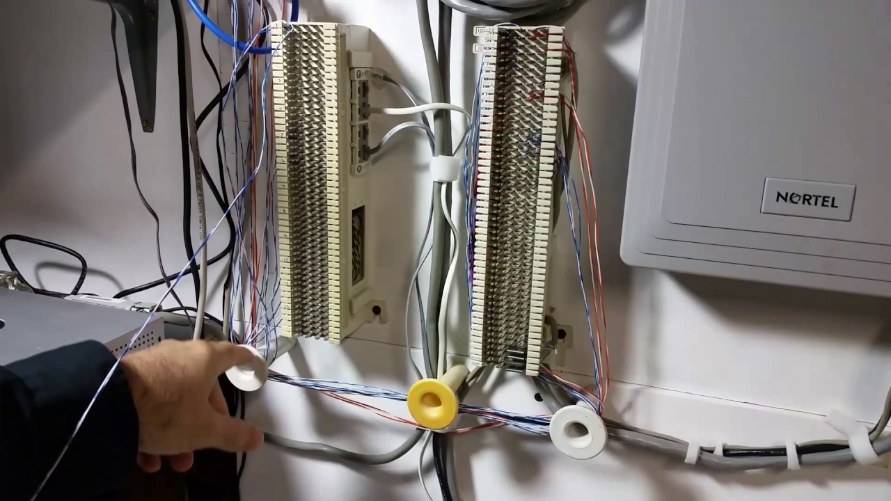
Mdf wiring diagram. Heres a very simple diagram that helps to explain the differences between in mdf and an idf. The mdf has a carrier side and a customer side commonly referred to as a side and b side. Install module wiring in accordance with the job drawings and appropriate wir ing diagrams. This document also explains how to install and wire telephones. The borg cube wiring diagram. User smanual 50.
Refrigeration circuit principle diagram mdf 333 15 refrigeration circuit welding points mdf 333 16 refrigeration circuit principle diagram mdf 537 17. Some panels support extended addressing. The idf intermediate distribution facility is optional and. A customer mdf is supplied and installed by the builders owners or customers cabling provider as part of the building telecommunications cabling. Cisco collective merced college semester 3 threaded case mdf idfs closets classrooms backbonean intermediate distribution frame idf is a distribution frame in a central office or customer premises which cross connects the user cable media to individual user line circuits and may serve as a distribution. The following information is included in this document.
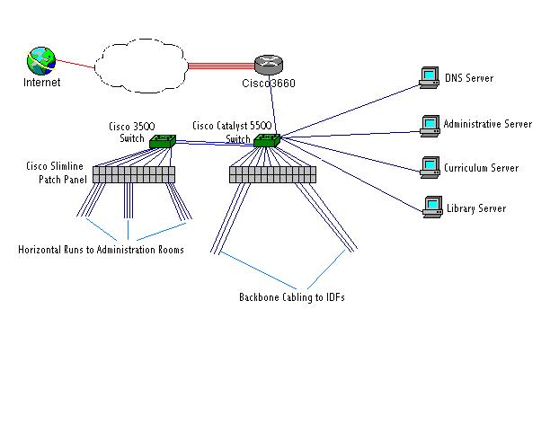
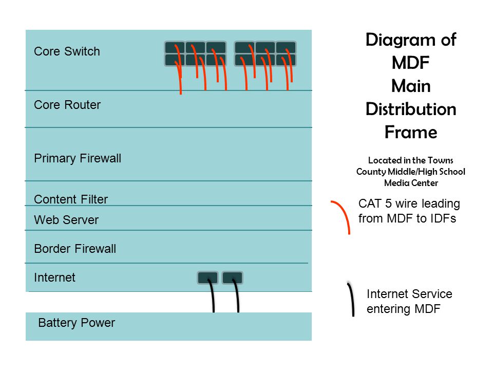
Each and every site will have whats referred to as an mdf that is the main distribution facility. You can see in this mdf display is the internet connection and any other wan connections that might be coming into the main part of the network. Media gateway connections to the mdf on page 35 mdf connections to stations and the public switched telephone network on page 43 connect the necessary telephone trunking and peripheral equipment using the information in installing and wiring telephones and trunks on page 71 and installing and wiring telephone power supplies on page 109. Installing the main distribution frame on page 13 installing the patch panel on page 29. The mdf is a termination point within the local telephone exchange where exchange equipment and terminations of local loops are connected by jumper wires at the mdf. This module is intended for power limited wiring only.
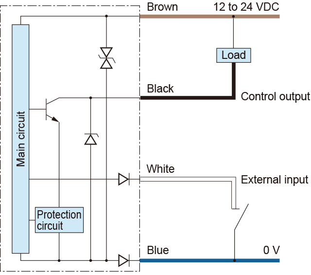
Test data 39. All wiring must conform to applicable local codes ordinances and regula tions. Parts loyout 49. Connect media gateways to the mdf and how to connect the mdf to the public switched telephone network pstn. Wiring diagram 34 circuit diagram 37 components on pcb. All cable copper pairs supplying services through user telephone lines are terminated at the mdf and distributed through the mdf to equipment within the local exchange eg.
Your file servers your web servers and all of your centralized equipment is usually located at this mdf.
Gallery of Mdf Wiring Diagram