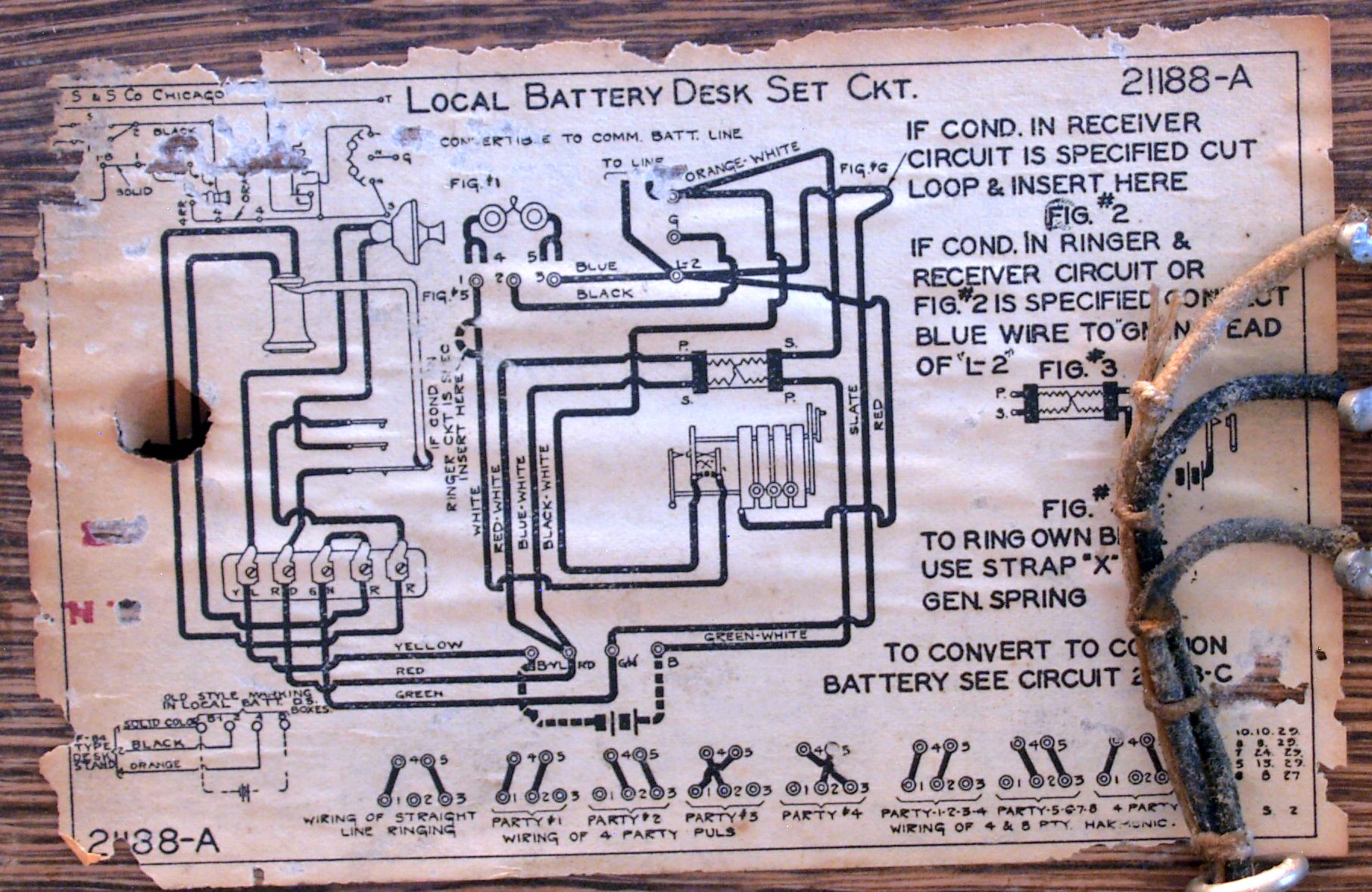
Comes ready to glue on your old telephone apparatus or put in a small picture frame. Old telephone magnetos produce ac electricity by passing a wound coil past a positive and negative charged fields.

Lf 7505 Figure 1 The Basic Wall Phone Diagram Of A Magneto
Magneto phone wiring diagram. Because of the technological improvements to telephones during the lifetime of the magneto telephone. Early sportster installation 1277 view. This produces a charge at the core of the armature or coil. Early model harley 74 magneto installation 1274 view. Actual size is 6 x 8 12. With this sort of an illustrative guidebook you are going to have the ability to troubleshoot avoid and total your assignments without difficulty.
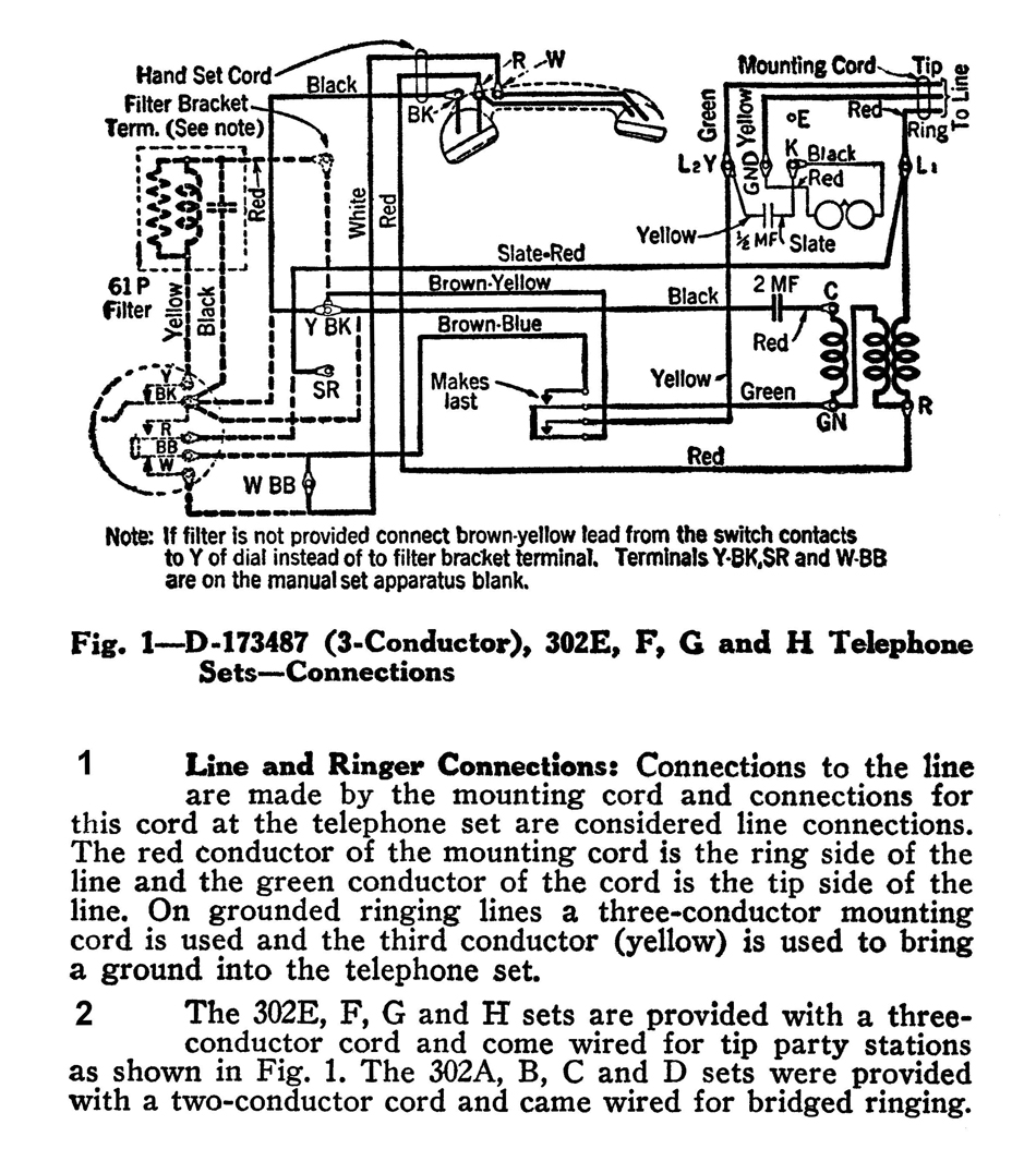
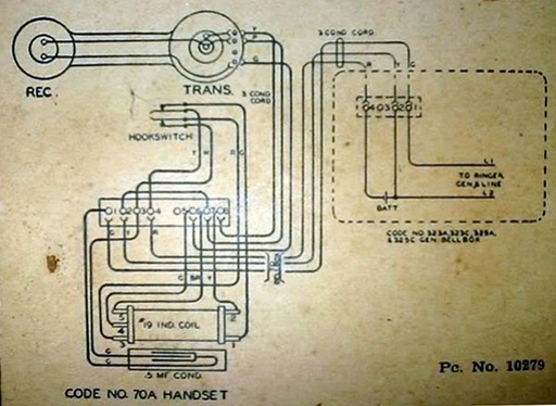
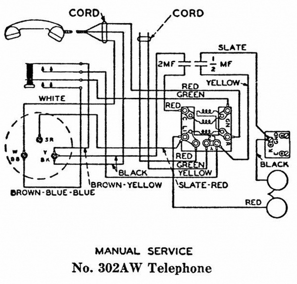
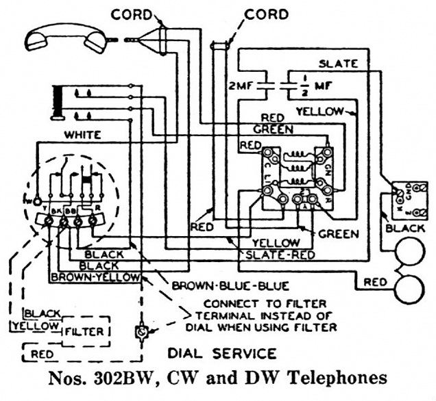
Here is a wiring diagram for a western electric telephone magneto and a candlestick telephone. The older mags put out about 80. Search for the phone model and wiring or schematic eg. Generally the information in the library is limited to equipment that was made prior to 1980. North 5h6 wiring this is a library of basic schematics wiring diagrams and other information that can be useful to anyone interested in restoring or repairing vintage telephone equipment. The circuit diagram describes the process for conversion from magneto to either automatic or cb common battery.
In this diagram the bell and generator are shown separated one from the other that the equipment may be fully understood but it is generally the custom to purchase these set up in one box the hook for the receiver being at one side the crank handle on the other and the. Harley big twin 70 and later installation. Briggs and stratton magneto wiring diagram you will want a comprehensive expert and easy to comprehend wiring diagram. External coil wiring diagram. Harley 74 horizontal style installation 1276 view. Telephone circuits and wiring.
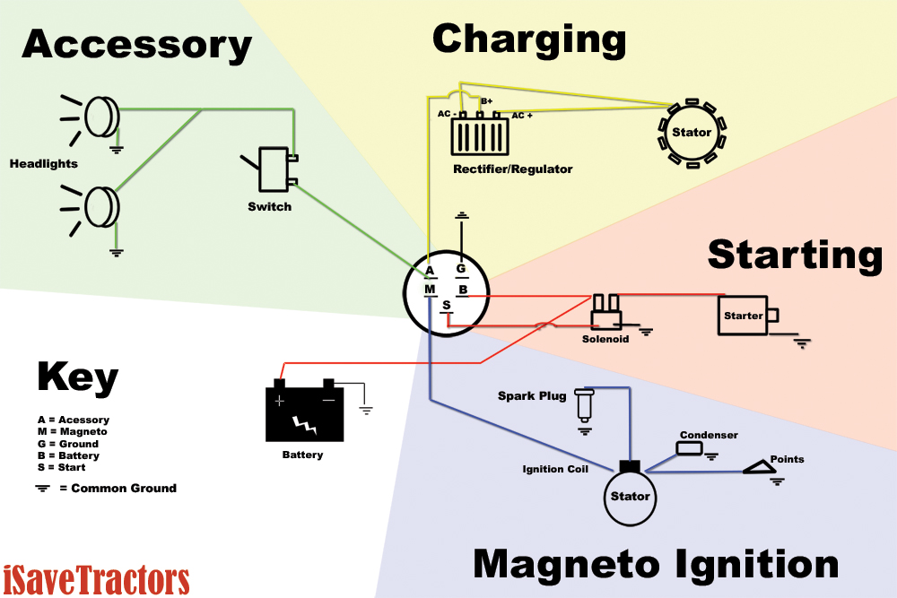
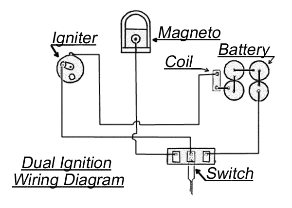
In both instances there is minor strapping change and also replacement of the induction coil the receiver and transmitter capsules. Late model harley 74 magneto installation 1274l view. A old telephone magneto produces from 6 to 110 volts. The figure given on the next page shows the line diagram of the magneto ignition system. Lines with magneto generator. In this case as shown we can have rotating magneto with fixed coil or rotating coil with fixed magneto for producing and supplying current to the primary the remaining arrangement is the same as that of a battery ignition system.


