Tech lpg controller installation manual and controller programming manual to perform the lpg level indicator calibration you should fill the lpg tank up following these steps. Go to the lpg station.

Gas Kit Installation Guide Carburetor Electrical
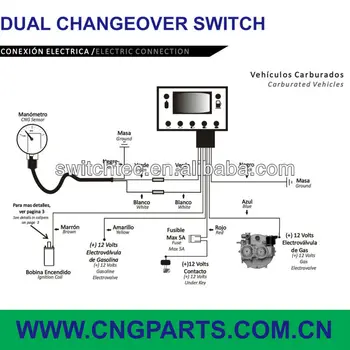
Lpg switch wiring diagram. The source is at the sw1 where the hot is connected to. This site is merely. Featuring wiring diagrams for single pole wall switches commonly used in the home. Press and hold the bg button on the switchboard. Switch wiring shows the power source power in starts at the switch box. Turn off the ignition switch while still pressing the bg button.
Wiring a single pole light switch. Hey doing it yourself is great but if you are unsure of the advice given or the methods in which to job is done dont do it. This light switch wiring diagram page will help you to master one of the most basic do it yourself projects around your house. Circuit electrical wiring enters the switch box. Lpg wiring diagram pdf wiring diagram is a simplified conventional pictorial representation of an electrical circuit. How to wire a single switch.
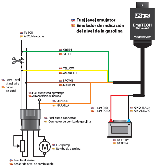
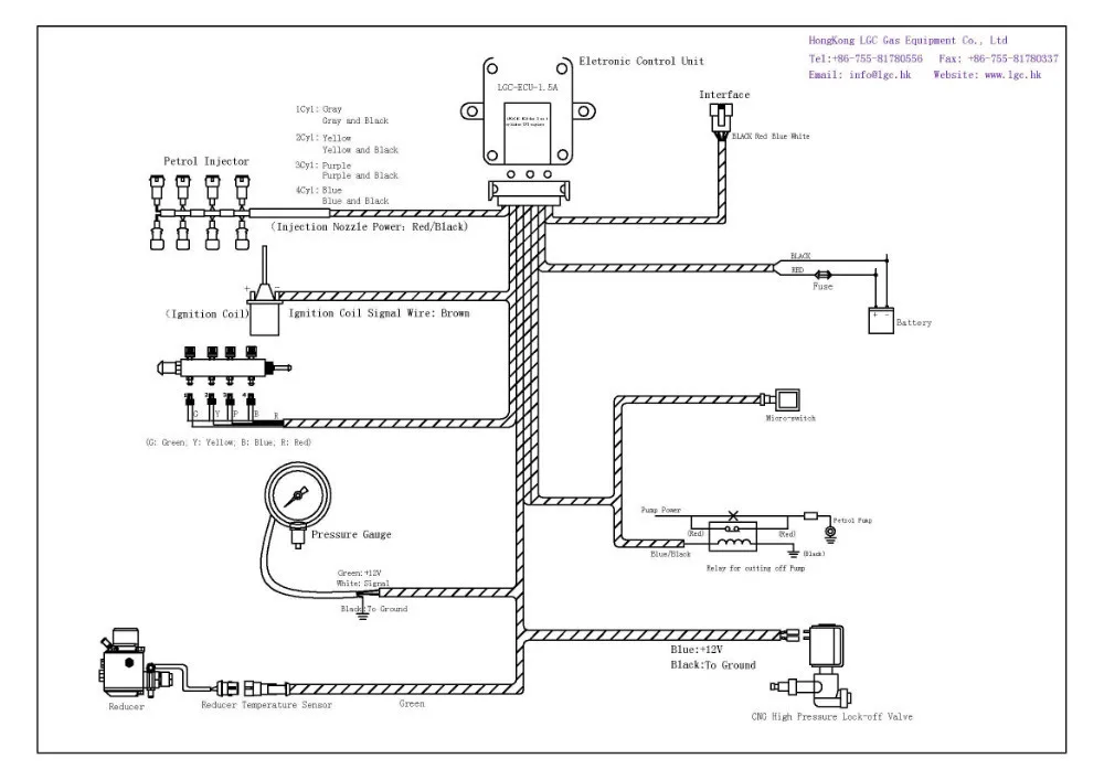
Ive had some more thoughts about it between now and when i last posted and was thinking of running the priming solenoid off a momentary switch button next to the isolation switch on the lower dash ie power from ignition to lpg switch that opens the tank and pre vapouriser solenoids to the button switch that only feeds power to the priming solenoid while the button is depressed. It shows the components of the circuit as simplified shapes and the faculty and signal contacts in the middle of the devices. 3 way switched outlet wiring. Explanation of wiring diagram 1. Keep the engine on. Three wire cable runs between the switches and the outlet.
In this diagram two 3 way switches control a wall receptacle outlet that may be used to control a lamp from two entrances to a room. This circuit is wired the same way as the 3 way lights at this link. Release the bg button the diodes will.
Gallery of Lpg Switch Wiring Diagram