Loop Powered Transmitter Wiring Diagram

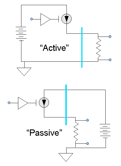
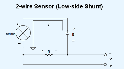
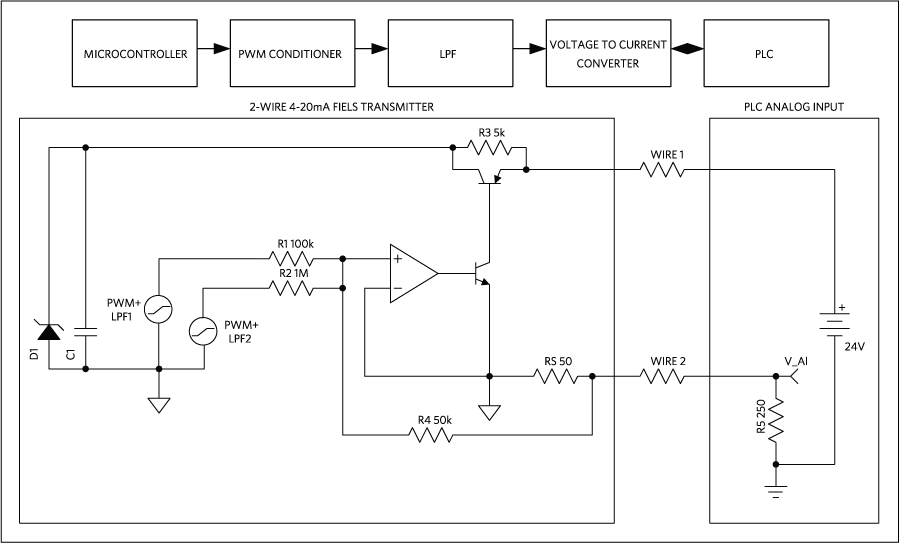
The right side of the triangle is labeled i and refers to the source of current or the power supply. A separate power supply is required for both the transmitter and control panel.

7 Loop Powered Signal Isolator Wiring Diagrams Ato Com

7 Loop Powered Signal Isolator Wiring Diagrams Ato Com

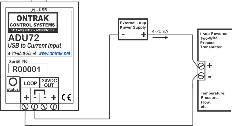
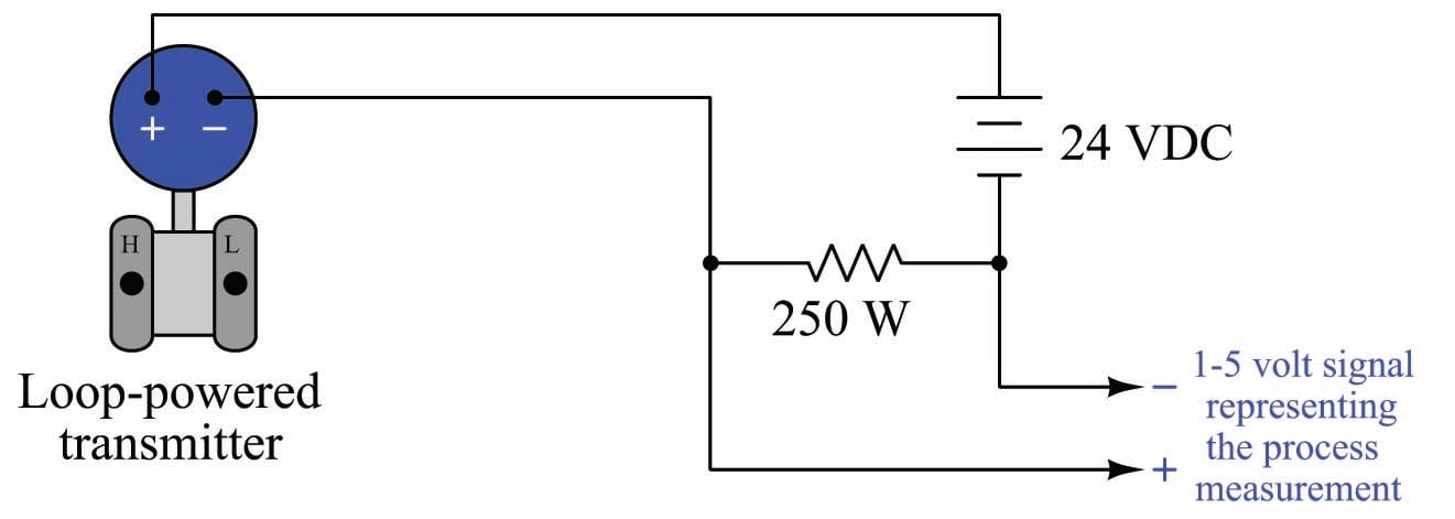
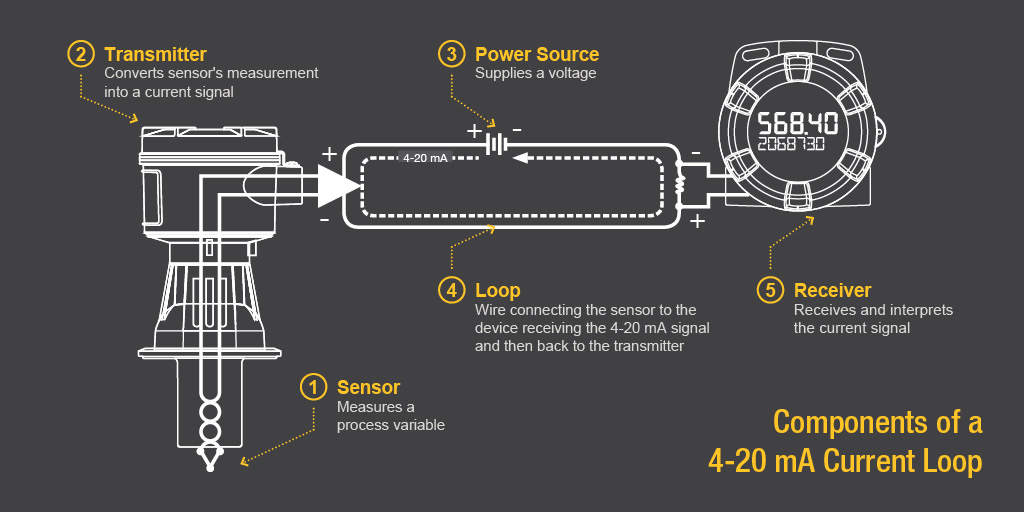
Loop powered transmitter wiring diagram. This is a typical wiring diagram of a loop powered signal isolator get energy from the input and 4 wire transmitter detailed parameters of loop powered signal isolator ato s sinir 502e are in the product page. This configuration supplies power and 4 20ma signal over a two wire loop connection between the transmitter and the control panel. The current allowed by the transmitter is called the loop current and it is proportional to the parameter that is being measured. Two wire loop powered transmitters. As shown in the diagram above current supplied from the power supply flows through the loop wires with resistance rw to the transmitter and the 4 20ma transmitter regulates the current flow within the loop. Wiring diagram of loop powered isolator with external powered 4 wire transmitter.

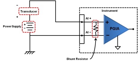
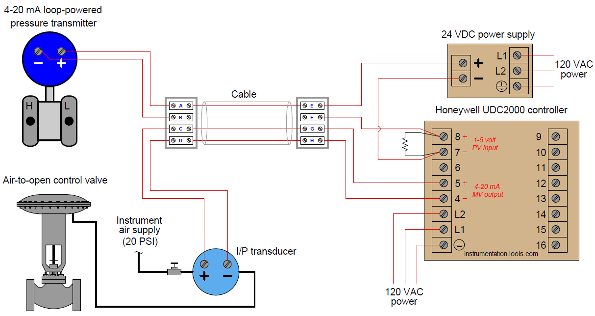
Dashed lines in instrument drawings represent individual copper wires rather than whole cables terminal blocks where wires connect are represented by squares with numbers in them. A transmitter analog output loop contains the transmitter power supply and the receiving device such as a plc. Each instrument bubble in a loop diagram represent an individual device with its own terminals for connecting wires. The actual wiring between the transmitter and the power supply depends upon whether it is a 2 wire or a 4 wire type. Introduction to the two wire transmitter and the 4 20ma current loop the left side is labeled t and refers to transmitter. The base of the triangle is labeled r and refers to receiver.

A 4 wire transmitter has 2 wires connected to a power supply and 2 signal wires connected to the plc.

Gallery of Loop Powered Transmitter Wiring Diagram

Edn The Self Powered Current Loop Still A Viable
Download Now
Edn The Self Powered Current Loop Still A Viable
Adu72 Usb To Current Input Interface 0 20ma 4 20ma
Download Now
Adu72 Usb To Current Input Interface 0 20ma 4 20ma
7 Loop Powered Signal Isolator Wiring Diagrams Ato Com
Download Now
7 Loop Powered Signal Isolator Wiring Diagrams Ato Com
Active Vs Passive Output And Two Wire Vs Four Wire
Download Now
Active Vs Passive Output And Two Wire Vs Four Wire
China Two Wire Loop Powered 0 5v 0 10v To 4 20ma Transmitter
Download Now
China Two Wire Loop Powered 0 5v 0 10v To 4 20ma Transmitter
4 20 Ma Current Loop Transmitter Modules Microstar
Download Now
4 20 Ma Current Loop Transmitter Modules Microstar
2 Wire 4 20ma Sensor Transmitters Increasing Sensor Power
Download Now
2 Wire 4 20ma Sensor Transmitters Increasing Sensor Power
Edn Design Tradeoffs For Loop Powered Transmitters
Download Now
Edn Design Tradeoffs For Loop Powered Transmitters
The Hart Digital Analog Hybrid Standard Digital Data
Download Now
The Hart Digital Analog Hybrid Standard Digital Data
Cn0314 Circuit Note Analog Devices
Download Now
Cn0314 Circuit Note Analog Devices
Planet Analog 4 Wire Current Loop Sensor Transmitters
Download Now
Planet Analog 4 Wire Current Loop Sensor Transmitters
How To Make 4 20 Ma Current Loop Measurements
Download Now
How To Make 4 20 Ma Current Loop Measurements
Back To Basics The Fundamentals Of 4 20 Ma Current Loops
Download Now
Back To Basics The Fundamentals Of 4 20 Ma Current Loops
Fundamentals System Design And Setup For The 4 To 20 Ma
Download Now
Fundamentals System Design And Setup For The 4 To 20 Ma
All About Plc Analog Input And Output Programming
Download Now
All About Plc Analog Input And Output Programming
Tipd158 Low Cost Loop Powered 4 20ma Transmitter Emc Emi
Download Now
Tipd158 Low Cost Loop Powered 4 20ma Transmitter Emc Emi
When Is A 4 20 Ma Output Needed On My Digital Panel Meter
Download Now
When Is A 4 20 Ma Output Needed On My Digital Panel Meter
How To Implement A 4 20ma Transmitter With The Max12900
Download Now
How To Implement A 4 20ma Transmitter With The Max12900
Pressure Control Loop Wiring Connections Instrumentation Tools
Download Now
Pressure Control Loop Wiring Connections Instrumentation Tools