Lead lag pump control wiring diagram all about hydronic multiple boiler systems industrial controls lead lag pump control wiring diagram wiring diagram is a simplified usual pictorial representation of an electrical circuit. P 2 or p 1 no matter which pump is selected as the lead pump.

Magna 3 Q Amp A Wiring A Magna 3 Pumphvac Com
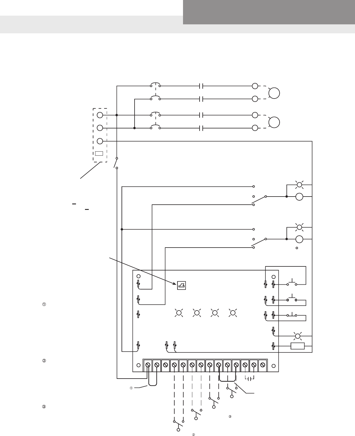
Lead lag pump control wiring diagram. Interconnecting cord courses might be revealed about where specific receptacles or fixtures should be on an usual circuit. Lead lag pump control wiring diagram whats wiring diagram. Board can be placed in either the r 1 or r 2 position. Lead relay for leadlag control 2. Failure to do so will result in damage to the controller t to t r to r shld to shld jumpers typical jumpers must be set correctly for the type of input you require. It shows the parts of the circuit as simplified shapes as well as the power as well as signal connections between the devices.
Symbols that represent the constituents within the circuit and lines that represent. Lead lag pump control wiring diagram building electrical wiring layouts reveal the approximate locations as well as affiliations of receptacles lights as well as irreversible electrical solutions in a structure. Function normal led again indicates lead pump operation. Wiring diagrams are made up of two things. 24 vac must be connected so that all ground wires remain common. Lag relay for leadlag control warning.
In case of lead pump failure the sequence will always index to the standby pump. A wiring diagram is a type of schematic which uses abstract pictorial symbols to exhibit every one of the interconnections of components in the system. It shows the components of the circuit as simplified shapes and the capacity and signal associates amongst the devices. A wiring diagram is a streamlined conventional pictorial depiction of an electric circuit. The leadlag manual selector switch s3 mounted on the pc. Variety of lead lag pump control wiring diagram.
Oe338 23 ll lead lag controller.
Gallery of Lead Lag Pump Control Wiring Diagram