Before you purchase a smart light switch youll need to figure out the type of switch you need. Use a butter knife or flat head.

Should The Kill Switch Be Hooked Up Positive Or Negative To
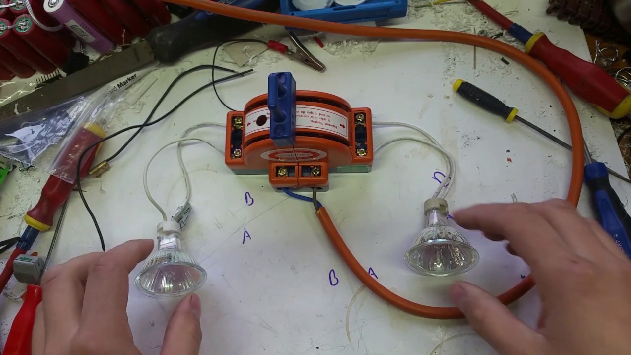
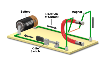
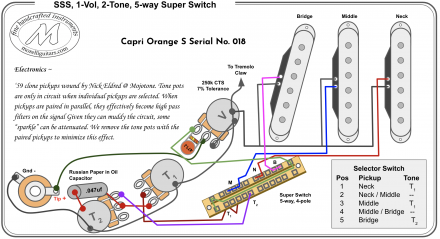
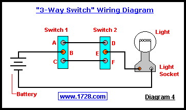
Knife switch wiring diagram. The neutral from the source is spliced through to the switch box using the white wire and in this diagram the white wire is capped with a wire nut. Click here for test switches spare parts. To clone the y axis. The two hot wires of three wire cable connect to a pair of brass colored traveler terminals on each switch. Click here for catalogproduct information pdf. This 3 way switch wiring diagram shows how to wire the switches and the light when the power is coming to the light switch.
This renewal parts guide reviews eatons general duty and heavy duty safety switch renewal part availability. Wire your circuit to the point where you are ready to install the switch. Since the electrical connections are exposed knife switches are never seen in household wiring. Outputs on the grbl board in the following diagram. These are available with different color handles to meet your specifications. In this updated diagram 3 wire cable runs between the receptacle and switch and the red cable wire is used to carry the hot source to the switch.
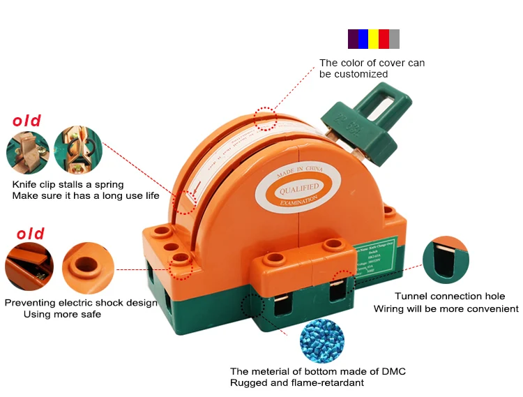
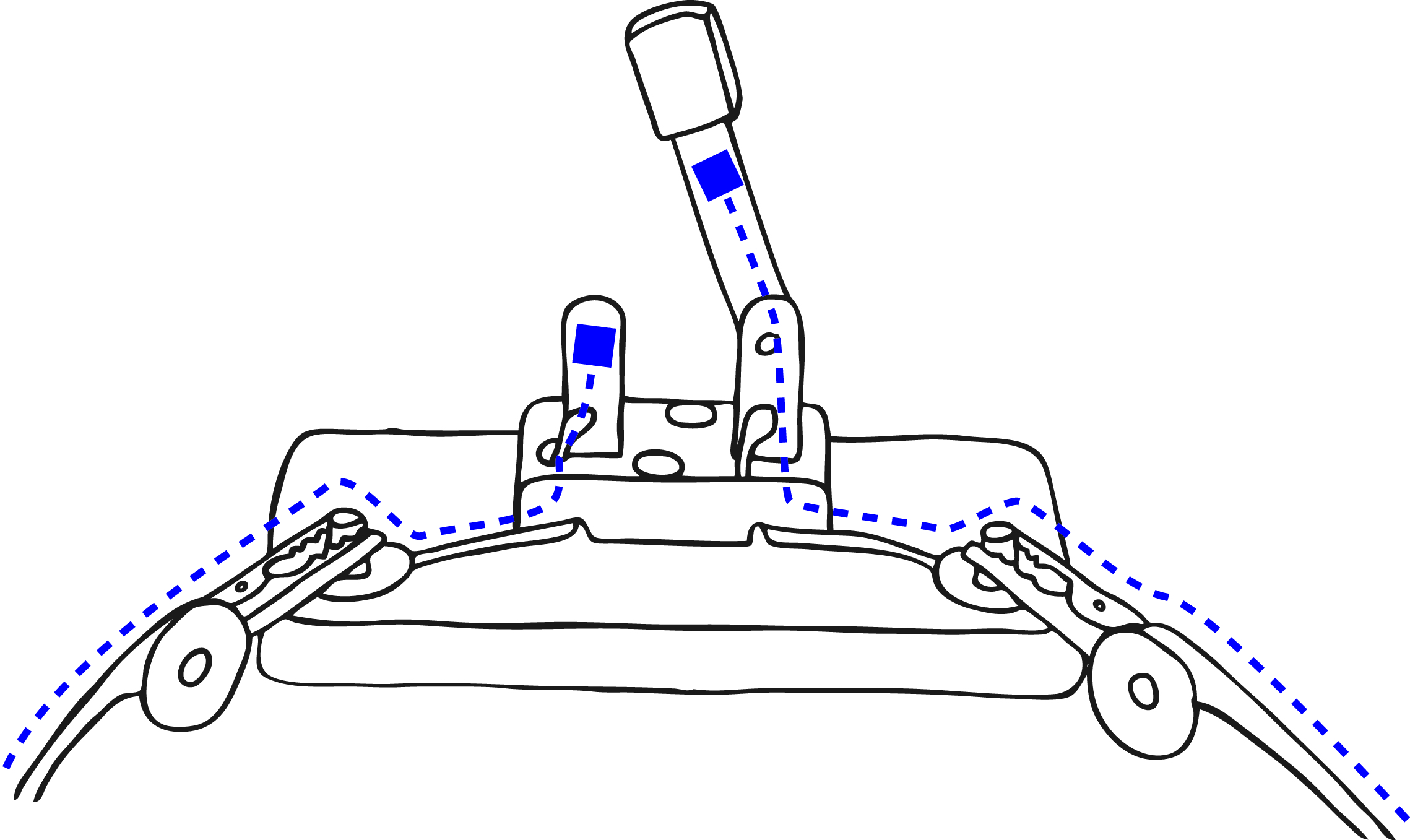
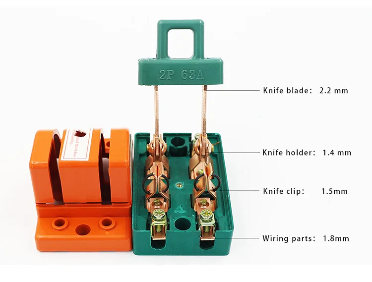
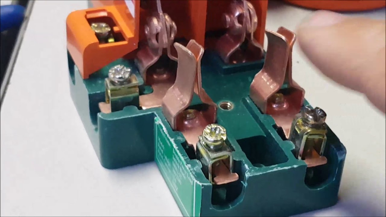
This disconnect may be a special breaker switch housed in an exterior box enclosure or it may. 3 way manual transfer switch manufacturer must have produced and sold ul 1008 listed manual transfer switches as a standard product for a minimum of 3 years. 3 way manual transfer switches shall be molded case circuit breaker type. The knife switch has a metal lever insulated at the free end that comes into contact with a metal slot. Always use the correct gauge wire. The wiring is simple but there is no indication if one of the switches is the schematic of the end sensor board which uses optocouplers.
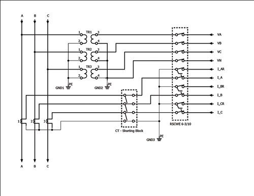
Pdf 202 kb 212013 safety switch renewal parts guide. For typical residential wiring jobs involving a standard 20 amp circuit 12 gauge wire is usually appropriate. Learn your existing wall switch and wiring setup. Connect them according to the section wiring limit. Referring to diagram 2 the wiring is very similar to diagram 1 except a switch has been added. Knife switch or fused switches are not acceptable.
Instruction manual grbl cnc controller. In this diagram the incoming hot wire attaches to the first switchs common dark colored terminal. Compare this to the typical household light. This instruction leaflet is presented to guide the installer when utilizing eaton switches with fine stranded wire. Electrical disconnects are switches that isolate all wiring in a home or other building from the source of power typically the utility power service. Also called the service disconnect this is the first disconnect device after the utility meter.
The 2rk1 test switch is a single potential pole knife blade switch with wiring connections on the side for those applications where space is limited.
Gallery of Knife Switch Wiring Diagram