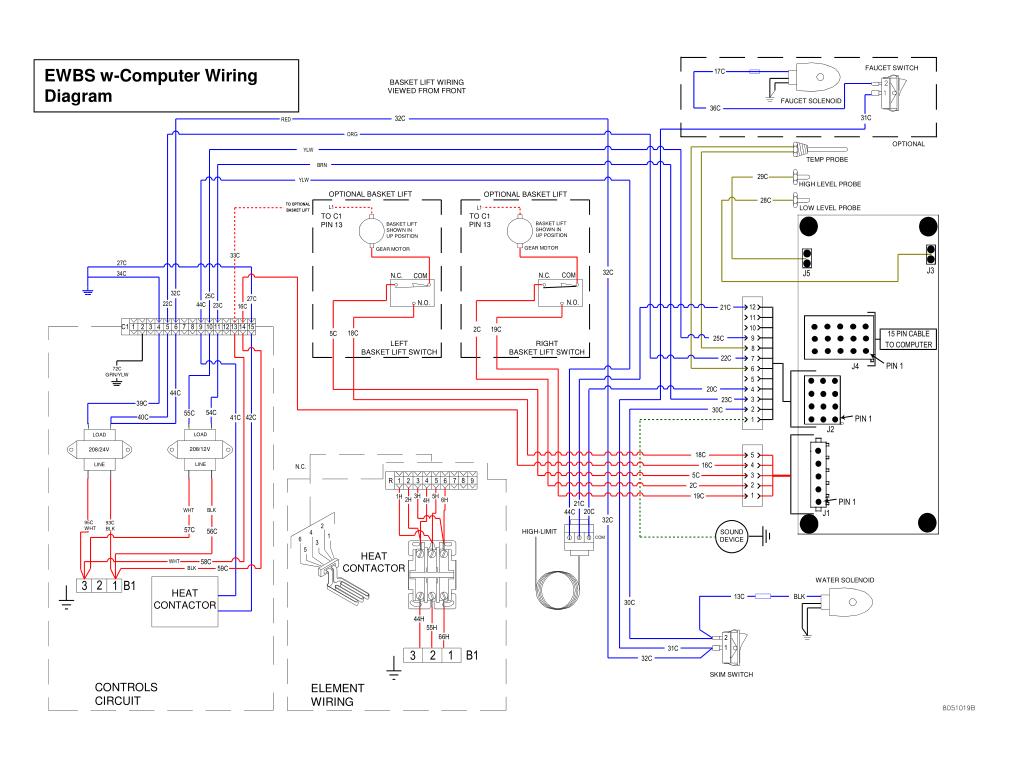
Thermostat wiring diagrams for heat pumps heat pump thermostat wire diagrams. Heat pumps are different than air conditioners because a heat pump uses the process of refrigeration to heat and coolwhile an air conditioner uses the process of refrigeration to only cool the central air conditioner will usually be paired with a gas furnace an electric furnace or some other method of heating.

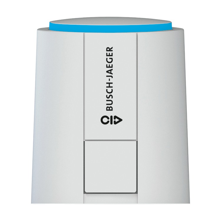
Technical Data 2010 2011 Busch Jaeger 5 Flush Mounted
Jaeger thermostat wiring diagram. If you have two r wires connect rc to rc and rrh to rh and remove the jumper. Color of wire and termination. Rc red wire power 24 vac rh or 4 red wire jumpered power 24 vac w white wire for heating enable y yellow wire for cooling enable. This diagram is to be used as reference for the low voltage control wiring of your heating and ac system. The line is connected to the l 1 terminal while neutral or second line is connected to the l 3 terminal. Note y2 some ac systems will have a blue wire with a pink stripe in place of the yellow or y wire.
Orange this wire connects to your heat pump if you have one. It is a red wire and comes from the transformer usually located in the air handler for split systems but you may find the transformer in the condensing unit. The wiring connection for both single phase 120v and 240v are same ie. In the diagrams below the dotted lines indicate optional wires that may not be applicable to your specific hvac system. Black color is neutral while red is phase or line and the yellowgreen wire is used for ground earth. R the r terminal is the power.
Thermostat wiring and wire color chart thermostat wiring colors code. My paperback and e book. Green the green wire connects to the fan. The common wire sometimes referred to as the c wire is whats responsible for delivering constant power to your thermostat. The water heater element is connected to the thermostat via t 2 as hot and l 4 as neutral. The basic heat ac system thermostat typically utilizes only 5 terminals.
Yellow the yellow wire connects to your compressor. For programmable thermostats and smart thermostats c wires are essential for setting a schedule or having your heat or air conditioner turn on at a desired temperaturewhile some units can run without a c wire even brands like nest recommend having one for optimal. The diagram below shows how a basic 4 wire thermostat is connected as indicated by the color code chart above. Always refer to your thermostat or equipment installation guides to verify proper wiring. Red now there can be two separate wires for this. White the white wire is what connects to the auxiliary heat on your system.
Refer to the blower chart for cfm requirements. If you have one r wire connect it to rh at the idevices thermostat and leave the blue jumper in place to rc.
