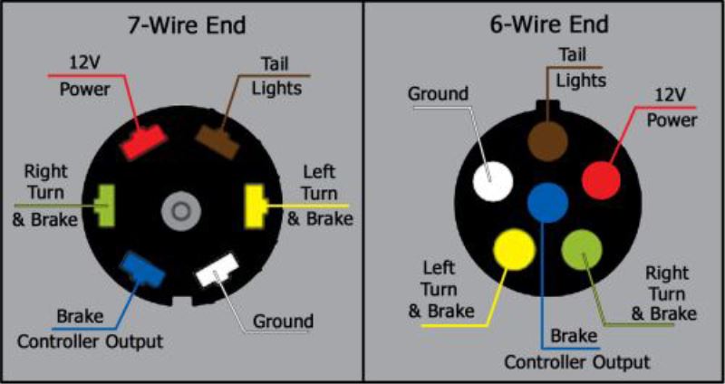
About the wiring harness. This is an installation and wiring guide for installing a gps tracking device in your cars or trucks.

2015 Range Rover Wiring Diagrams Wiring Diagrams
Inilex gps wiring diagram. Jul i dead headed the hpop and see no pressure with a manual gauge hooked up. Connecting the device to a garmin marine radar. Is marked by a sticker on the vtu showing gps this side up. Hard wire fleet car auto vehicle gps tracker with ignition kill switch control tracking device. Connecting the device to an external garmin sounder module. Lamp or horn connections.
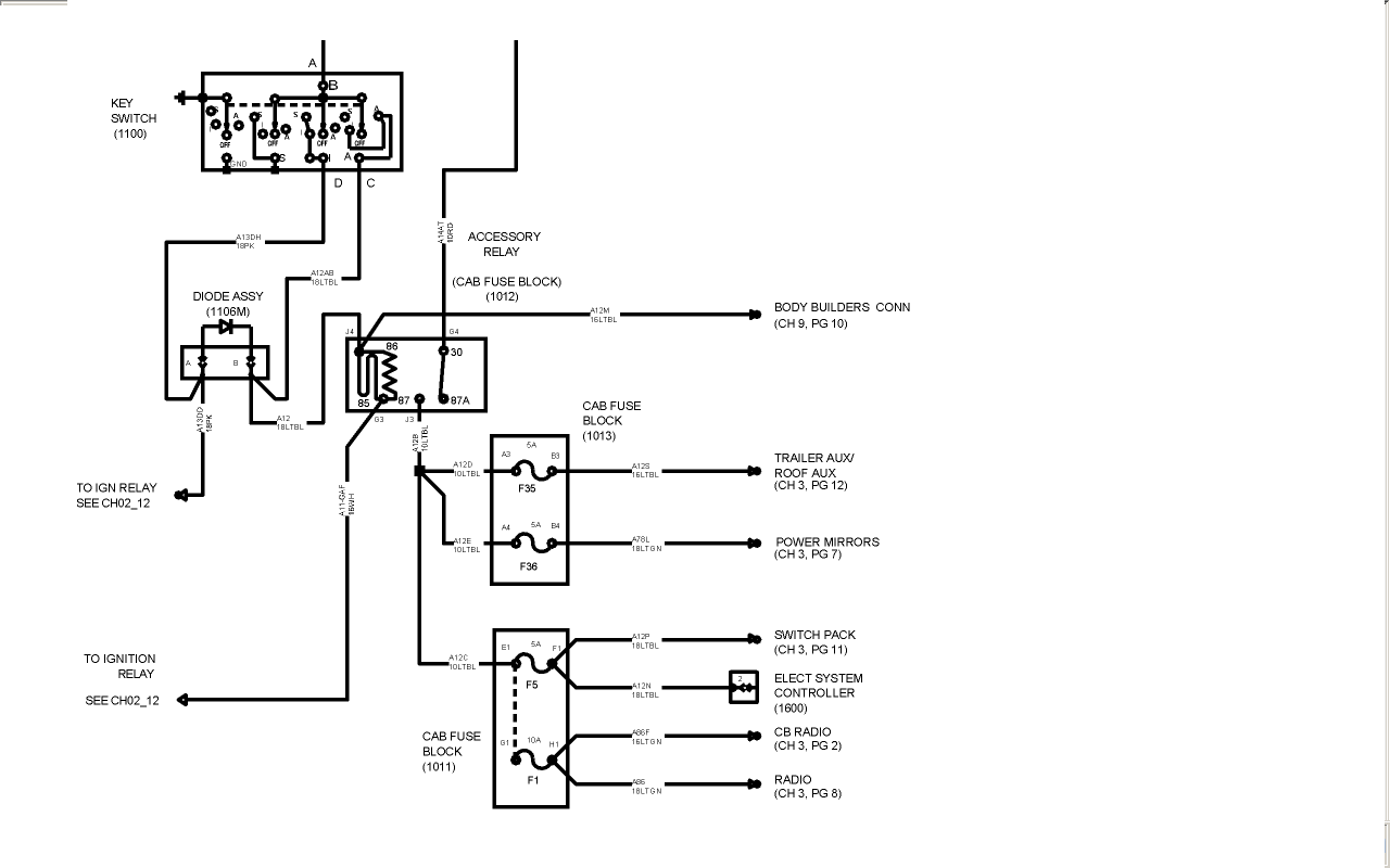
Passtime elite gps wiring diagram wiring diagram is a simplified standard pictorial representation of an electrical circuitit shows the components of the circuit as simplified shapes and the knack and signal links between the devices. Nmea 0183 connection considerations. Radar sonar and map sharing considerations. On inilex gps wiring diagram. See wiring diagram for details 4. 19112018 19112018 1 comments on 2004 ford 60 ipr wiring diagram join date.
Connect the wires according to the following table. Connect the wires to the vehicle use the wiring harness provided with the installation kit. As ford doctor mentioned the pcm completes the circuit for the ipr with battery voltage being applied to one terminal. Nmea 0183 connection diagram. Optional connections connect green input. If you came across this page as you were looking to install an.
Connecting the device to a transducer. Connecting the wiring harness to power. Do not plug the power cable into the vtu at this time.


