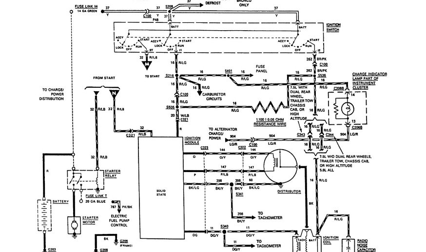
Ignition coil wiring diagram welcome to my web site this post will certainly go over concerning ignition coil wiring diagram. Dec 10 2016 automotive wiring diagram resistor to coil connect to distributor wiring diagram for ignition coil.

Ignition Upgrade Sr20 Tuning
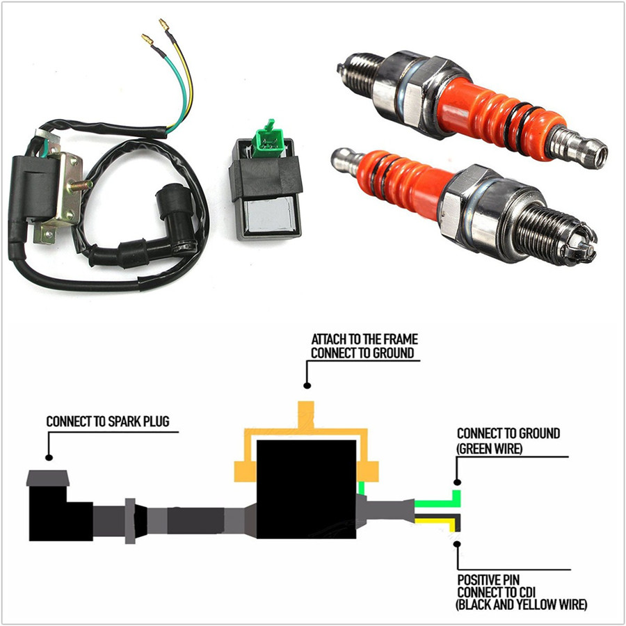
Ignition coil wiring diagram. Collection of mallory ignition wiring diagram. Ignition coil ballast resistor wiring diagram welcome to my internet site this blog post will certainly discuss concerning ignition coil ballast resistor wiring diagram. We have actually collected numerous pictures ideally this image works for you and assist you in discovering the answer you are looking for. Ignition coils of this type are usually a little larger than a soda can and are heavy. Through the thousand images on line regarding ignition coil condenser wiring diagram we all choices the top selections together with best resolution just for you all and this pictures is actually one of graphics collections in your greatest pictures gallery regarding ignition coil condenser wiring diagramlets hope you will think its great. Ignition system no start problem diagnostic manual.
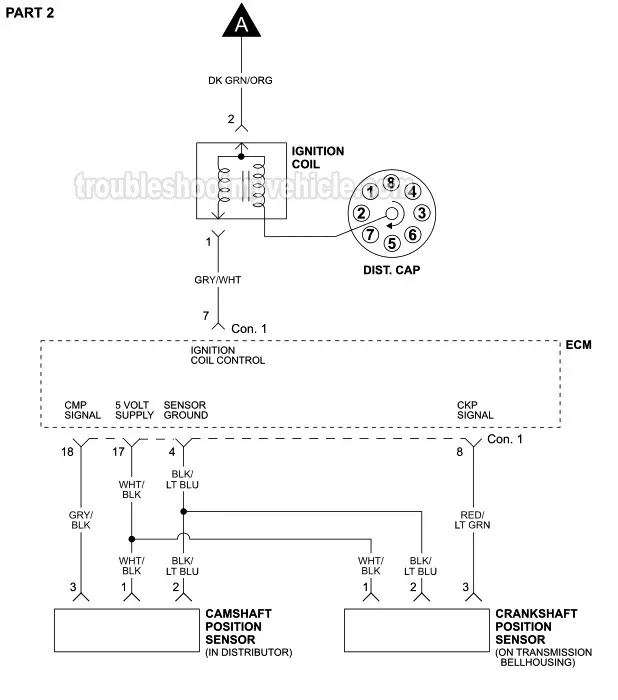
The coils which are the basis for ignition coils and alternators have very specific electronic. These coils had very simple wiring. Older model cars used the 12 volt ignition coils to provide power to the spark plugs. Diagnostic manual comes with. Because the output spark is very much higher voltage 20000v than the car battery 12v it doesnt care if the battery polarity is helping or hindering by a meager 12 to 14 volts in battery potential. All of the information you need to diagnose a no start problem caused by the ignition module or the ignition coil or the distributor pickup coil.
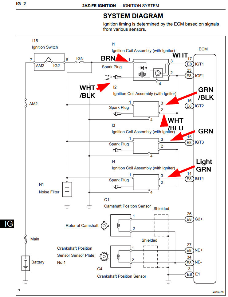
This video concentrates on coils from an electronic point of view and reading wiring diagrams. In the years when engines were a lot easier to work with a ballast resistor was used in order to prolong the life of the coil. Wiring diagram for ignition coil. Complete step by step testing instructions. They usually required only three wires. Wiring diagram for ignition system.
A wiring diagram is a simplified standard pictorial depiction of an electrical circuit. It shows the components of the circuit as streamlined forms as well as the power and also signal links between the tools. The simple fix for this is to reverse the two primary wire connections on the ignition coil. The spark plug wire the power wire and the ignition switch wire.
Gallery of Ignition Coil Wiring Diagram