This makes the procedure for assembling circuit simpler. Ididitamp039s direct fit camaro and firebird steering column hot rod ididit steering column wiring diagram.

Lg 2692 1967 Plymouth Barracuda Wiring Diagram Plymouth
Ididit wiring diagram. Ididit has been making the finest quality steering columns and related accessories for the hot rod and muscle car enthusiast for the past 30 years and continues to expand on that tradition. Touch the white wire with your test light and push down the brake pedal. This wire no matter what anyone says otherwise should never be hooked to anything other than the negative side of the horn relay. Many good image inspirations on our internet are the most effective image selection for ididit steering column wiring diagram. The black wire located on ididits gm style wiring harness that most of us may think is ground is actually for the horn wire. Please contact us if you dont find what you are looking for.
2008 chevy silverado headlight wiring diagram of 2008 chevy silverado headlight wiring diagram we collect plenty of pictures about ididit steering column wiring diagram and finally we upload it on our website. The diagram provides visual representation of a electric arrangement. We created these custom column forms for our universal series steering columns as a guide to help you determine what measurements youll need to in order to make your custom ididit column the way you want it. The white wire should be connected to the light tester when testing the brakes. Ididit gm shaft steering columns use a standard 3 78 inch. Custom column diagrams ididit is here to help you every step of the way.
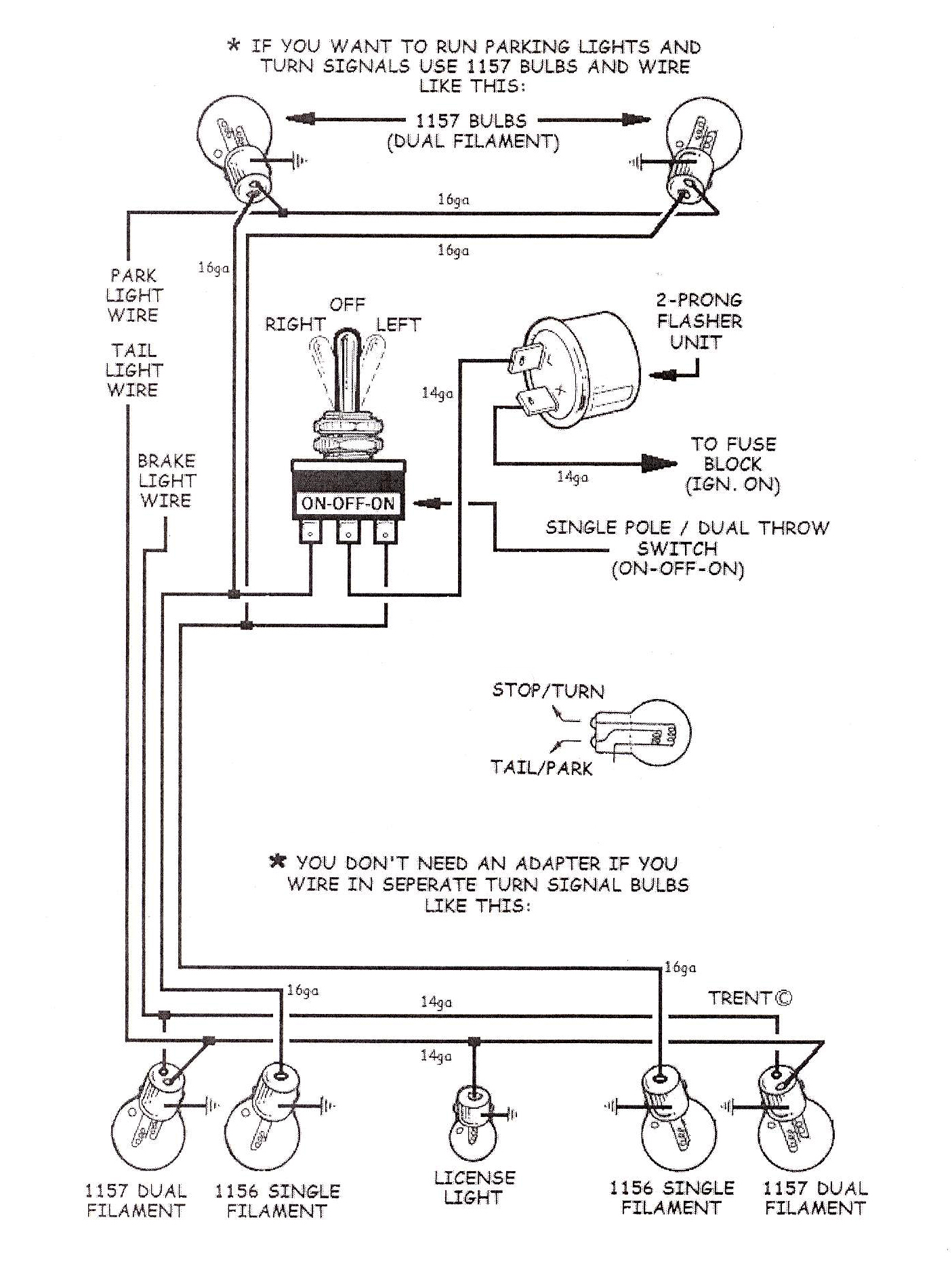
Find pdf installation instructions and other guides for your ididit product. Then attach the green and yellow wires together and press the brake pedal down once more. Turn signal test the purple wire should be connected to the test light when testing the turn signal. On the other hand the diagram is a simplified variant of this arrangement. A wiring diagram is a simplified standard photographic representation of an electrical circuit. It reveals the elements of the circuit as simplified forms and also the power and signal links in between the tools.
Gallery of Ididit Wiring Diagram