Connect the incoming power to the panel. An example of a wiring diagram for a motor controller is shown in figure 1.

Electrical Panel Board Wiring Diagram Pdf Free Downloads
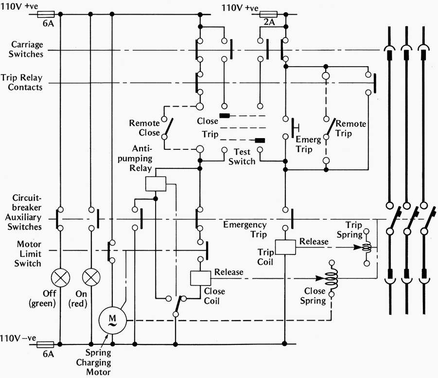
Ht panel wiring diagram. It on has one connection on the side of the box. Basics 9 416 kv pump schematic. A wiring diagram is a streamlined standard pictorial depiction of an electrical circuit. This will become clearer when you begin working with our control panel sample wiring diagrams in the exercises below. 4 after pulling all four wires through the conduit and into the equipment control box connect them to the proper terminals as indicated by the wiring diagram on the lid of the equipment control box. Its reliable operating mechanism also ensure safety of the user.
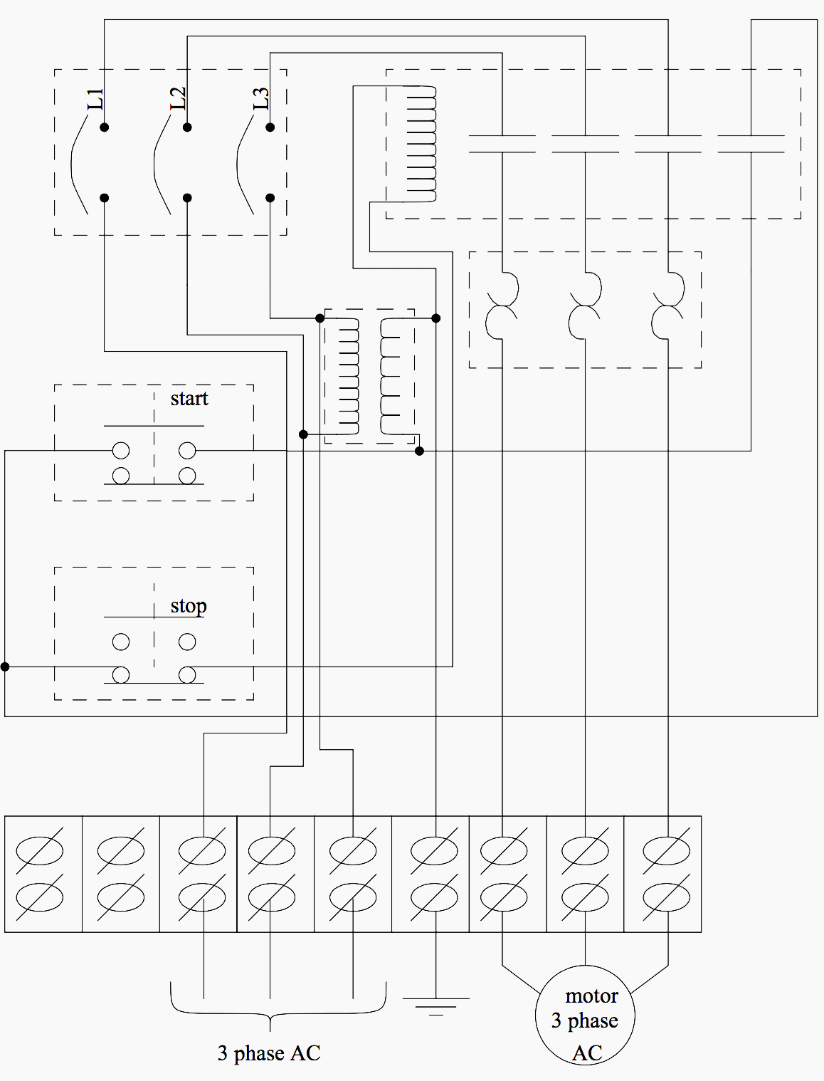
Three phase motor connection schematic power and control wiring installation diagrams. The panel is user friendly and easy to operate. Switch wiring diagrams a single switch provides switching from one location only. It shows the elements of the circuit as streamlined shapes and the power as well as signal connections in between the devices. Basics 8 aov elementary block diagram. Refer to the panel wiring diagram for the correct terminal connections for your system.
Single pole may sound simple but there are different ways to wire a single pole switch. Electrical wiring diagrams of a plc panel. Basics 11 mov schematic with block included basics 12 12 208 vac panel diagram. 5 configure the jumpers to the correct position as indicated by the wiring diagram on the lid of the equipment control box. There is a wire connecting the two then another wire leads from each subwoofer speaker and connects to only one positive and negative square on the side of the box. Basics 13 valve limit switch legend.
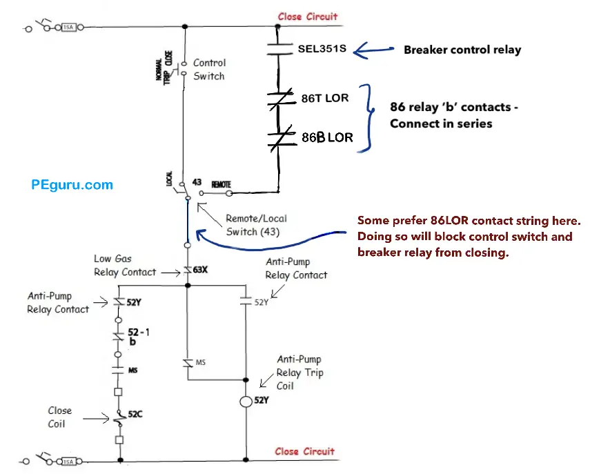
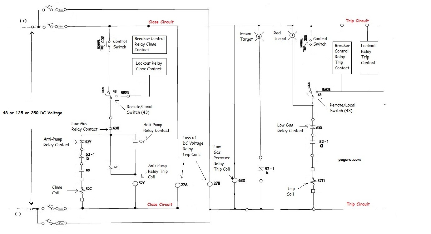
The panel is high in performance provide accurate results and require less maintenance. Dashed lines indicate a single purchased component. Basics 10 480 v pump schematic. Three phase motor connection stardelta without timer power control diagrams. This system uses 3 phase ac power l1 l2 and l3. A wiring diagram typically provides information regarding the family member placement and also arrangement of devices and also terminals on the devices in order to help in structure or servicing the tool.
Star delta y δ 3 phase motor starting method by automatic star delta starter with timer. How to tell if my 12 subs are bridged inside the box. The power can come from either the switch box or the fixture box and a set of electrical switch wiring diagrams will explain each of these scenarios to you clearly. Note that symbols are discussed in detail later. The next key advantage of ladder wiring diagrams over drawing circuits is the way they are physically laid out so that they are indexable meaning device names can give you the page and rung number that the device can be found. 11kv vacuum circuit breaker ht panel indoor type for protection of transformer ht capacitor generator ht motor feeder line.
Power to the panel must be appropriate to the control panel and pump motor 120 vac single phase for a 120 vac motor 240 vac single phase for a 240 vac motor etc. Basics 7 416 kv 3 line diagram. Basics 14 aov schematic with block included basics 15 wiring or connection. I have 2 rockford punch subs in a band pass box.
Gallery of Ht Panel Wiring Diagram