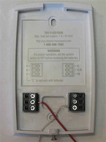
Metal jumper for thermostat rc and rh terminals. Color of wire and termination.

Thermostat Wiring Explained
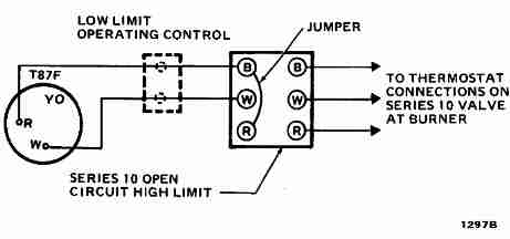
Honeywell thermostat wiring diagram 3 wire. A wiring diagram is a streamlined standard pictorial representation of an electric circuit. Heat pumps are different than air conditioners because a heat pump uses the process of refrigeration to heat and coolwhile an air conditioner uses the process of refrigeration to only cool the central air conditioner will usually be paired with a gas furnace an electric furnace or some other method of heating. At left the thermostat wiring diagram illustrates use of a honeywell t87f thermostat in a 2 wire application controlling a gas fired heating appliance. Thermostat wiring and wire color chart thermostat wiring colors code. Wiring diagrams help technicians to see how the controls are wired to the system. It reveals the parts of the circuit as streamlined shapes and also the power and also signal links in between the gadgets.
Please download these honeywell thermostat wiring diagram 3 wire by using the download button or right click on selected image then use save image menu. In the honeywell t87f thermostat series the single pole double throw switch makes closes one set of contacts when the temperature falls to turn on the heating appliance. Variety of honeywell thermostat wiring diagram 3 wire you can download at no cost. The thermostat makes a contact on both a rise and on a fall of room temperature. Electrical wiring for a honeywell thermostat. According to earlier the traces in a honeywell thermostat wiring diagram 3 wire signifies wires.
Occasionally the cables will cross. Electrical wiring question replacing honeywell t6160 room stat mains 3 wirewith horstmann drt2battery operated 2 wire. More about thermostat wiring. If we recommend placing a wire in a terminal do not move it to another terminal if we address it later in the guide. You have a single wire labeled w ob and we advise placing it in the ob terminal. R the r terminal is the power.
Thermostat wiring diagrams for heat pumps heat pump thermostat wire diagrams. However it doesnt imply link between the cables. At left the thermostat wiring diagram illustrates use of a honeywell t87f thermostat in a 3 wire application as a spdt single pole double throw switch such as used to control low voltage motors electric radiator valves zone valves. Injunction of two wires is usually indicated by black dot to the intersection of two lines. July 8 2018 by larry a. It doesnt control cooling and because its a mechanical thermostat it doesnt need power for internal functions so it has no c wire.
Again referring to the honeywell thermostat ct31a1003 wiring diagram you can see it requires only two wires r and w. After mounting the new thermostats wall plate we can re connect the wiring. More about replacing honeywell thermostat. It is a red wire and comes from the transformer usually located in the air handler for split systems but you may find the transformer in the condensing unit. Collection of honeywell thermostat wiring diagram 3 wire.


