Trailer voltage and current distributions 17 a. Electrical fires and typical causes 24 10.
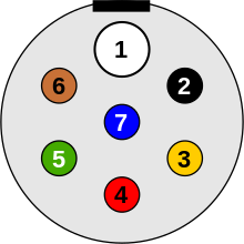
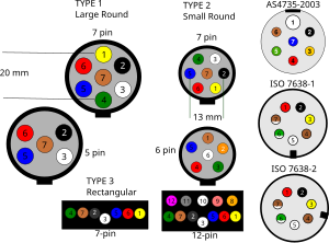
Iso Standards For Trailer Connectors Wikipedia
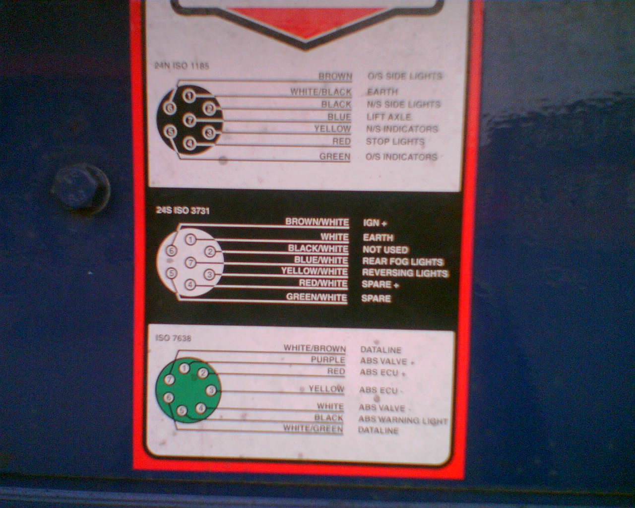
Hgv trailer wiring diagram. Good practice guide 25 a. Typical trailer wiring diagram and schematic. Complete with a color coded trailer wiring diagram for each plug type this guide walks through various trailer wiring installation solution including custom wiring splice in wiring and replacement wiring. Hgv trailer wiring diagram uk hgv trailer wiring diagram uk folks understand that trailer is a car comprised of quite complicated mechanisms. Click on the image below to enlarge it. Road trains 20 d.
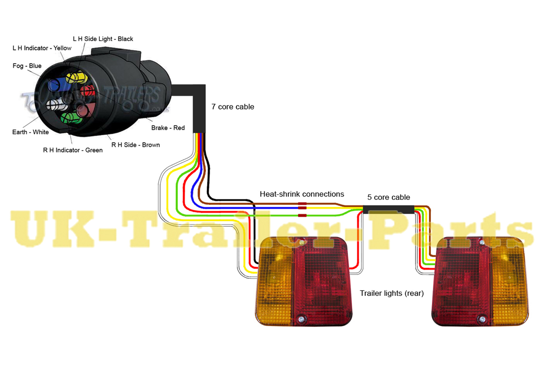
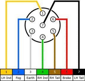
The second diagram shows two brake lights two indicators two side lights and a fog light. This vehicle is designed not just to travel 1 place to another but also to take heavy loads. Single trailer 17 b. Here is the diagram for 7 pin connector. This guide will be talking hgv trailer wiring diagram ukwhat are the advantages of understanding these knowledge. If your vehicle is not equipped with a working trailer wiring harness there are a number of different solutions to provide the perfect fit for your specific vehicle.
The first diagram is a simple set up of two brake lights two indicators and two side lights. Various connectors are available from four to seven pins that allow for the transfer of power for the lighting as well as auxiliary functions such as an electric trailer brake controller backup lights or a 12v power supply for a winch or interior trailer lights. Only the blue brake and white ground wires are different. Trucktrailer wiring plugs 14 6. Trailer wiring diagrams trailer wiring connectors. Below is the generic schematic of how the wiring goes.
You can use a circuit tester to verify connections. Check out or trailer wiring diagrams for a quick reference on trailer wiring. Truck trailer cable choice 23 a. Connector choice and maintenance 22 a. Click on the image below to enlarge it. To connect the electric system of your trailer to the vehicle you will be using special connector.
White pin to your ground. These 2 wire diagrams fit the needs for most trailers. Here are two wiring diagrams for the 7 pin n type trailer electrical plug. Trailer wiring diagrams trailer wiring connectors various connectors are available from four to seven pins that allow for the transfer of power for the lighting as well as auxiliary functions such as an electric trailer brake controller backup lights or a 12v power supply for a winch or interior. Extrapolate the same expansion for additional axles. Above we have describes the main types of trailer wiring diagrams.
4 pin trailer wiring diagram. It can transfer electricity better hence the connector is suggested for higher level electric in the vehicle. The image above shows a single axle trailer and the next image shows wiring for tandem axles. The below information is for reference and is commonly used throughout the industry but can vary depending on who built the trailer. This hgv trailer wiring diagram model is more suitable for sophisticated trailers and rvs.


