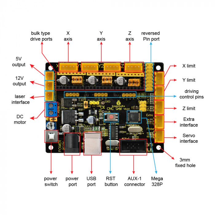
Keyestudio cnc grbl v09 is a motherboard developed for various robots such as laser engraving cnc writing robot and so on. We would like to show you a description here but the site wont allow us.

A Simple Diy Arduino Controlled Cnc Machine Pen Plotter Or
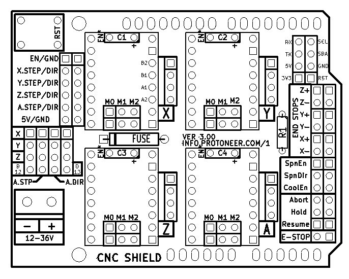
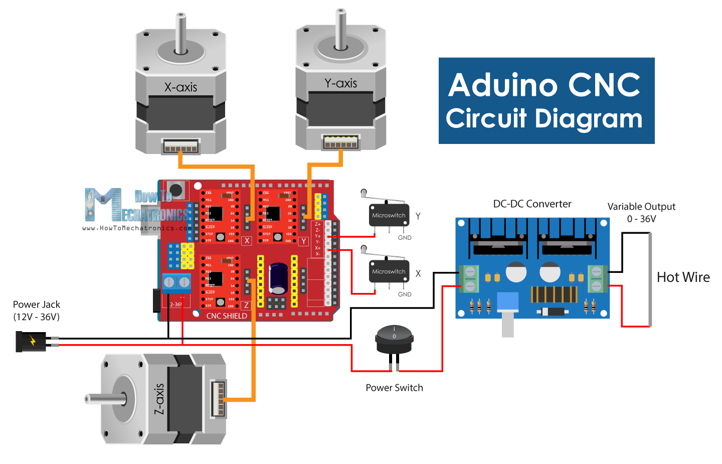
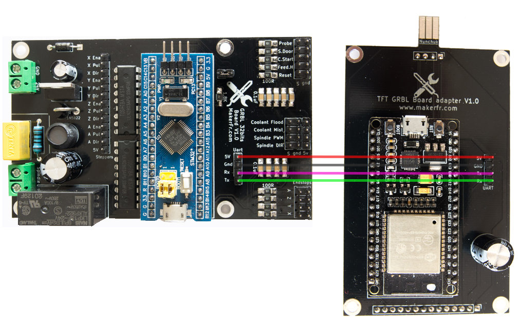
Grbl wiring diagram. Grbl 11 pinouts grbl 11 has all of the following output provided for operating the cnc machine or laser machine. The grbl shield goes on top of the arduino uno. Outputs on the grbl board in the following diagram. Grbl as a language helps the computer communicate to the machine. But for the sake of this tutorial we just need to know two things. Drivers and utilize 4 motors on a three axis system since.
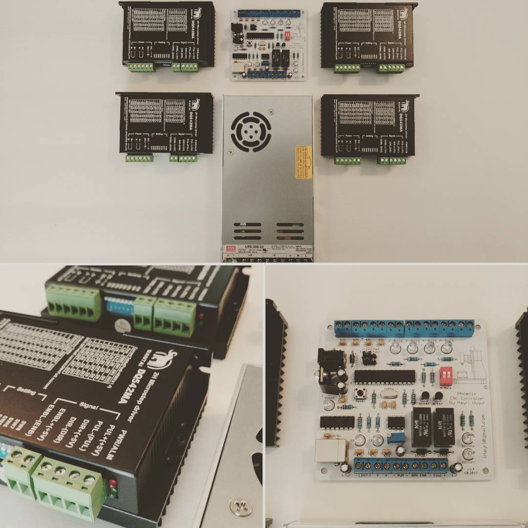
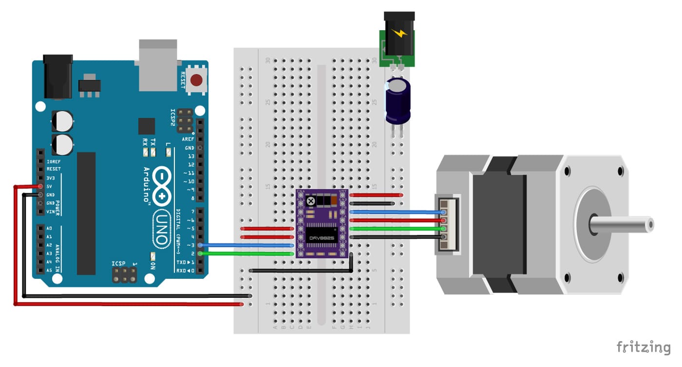
The big easy driver is a stepper motor driver board for bi polar stepper motors up to the basic wiring diagram is shown below in figure 3. Keyestudio cnc grbl v09. All of these signals are routed through the grbl shield to the proper places for the stepper drivers and output connectors. Wiring diagrams for 3dtek specific grbl gecko g540 combo. The ends of travel of an axis just wire two limit switches in parallel to the axis limit pin and ground. It is designed to work with grbl 09 to 11f.
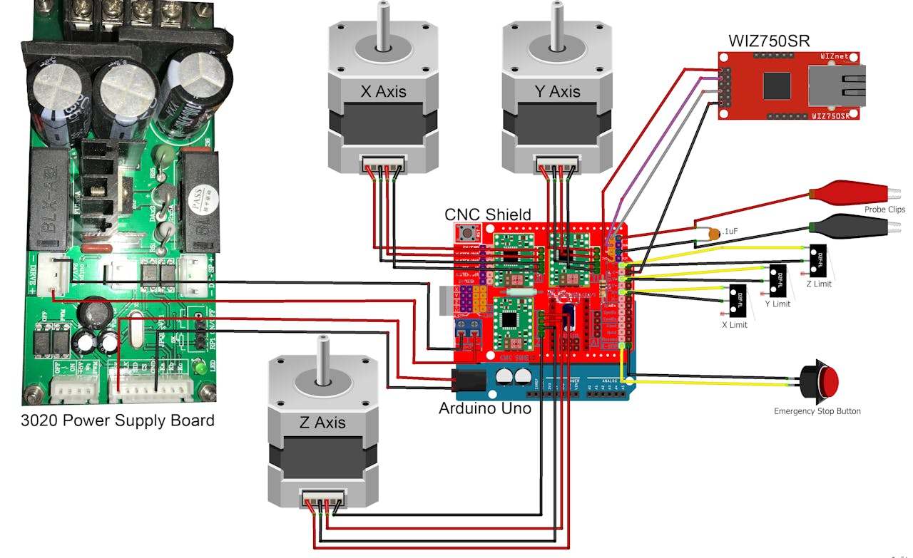
The arduino uno pinout guide includes information you need about the different pins of the arduino uno microcontroller and their uses. The guide also discusses different communication protocols used by the arduino and a detailed diagram of the arduino uno board. Instruction manual grbl cnc controller. These may or may not be useful for other gecko use cases. Power supply analog and digital pins and icsp. I am trying to connect the cnc shield to the tb drivers because the only point of a cnc shield is to hold those pololu style stepper driver boards.
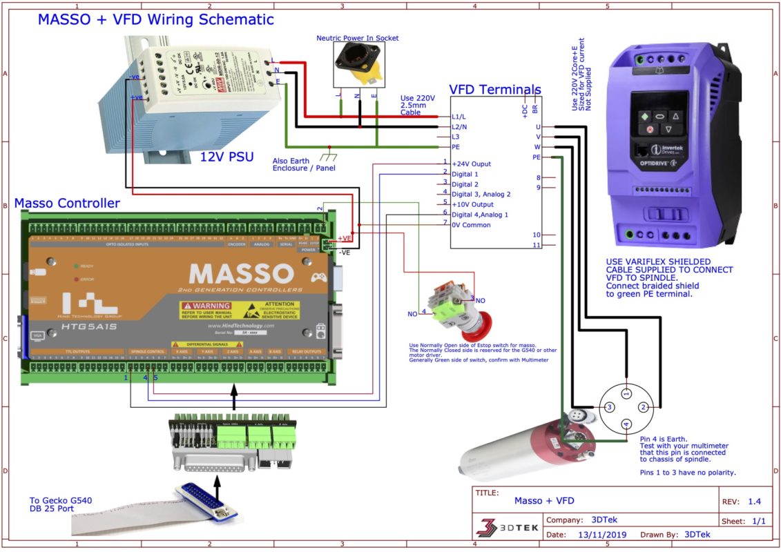
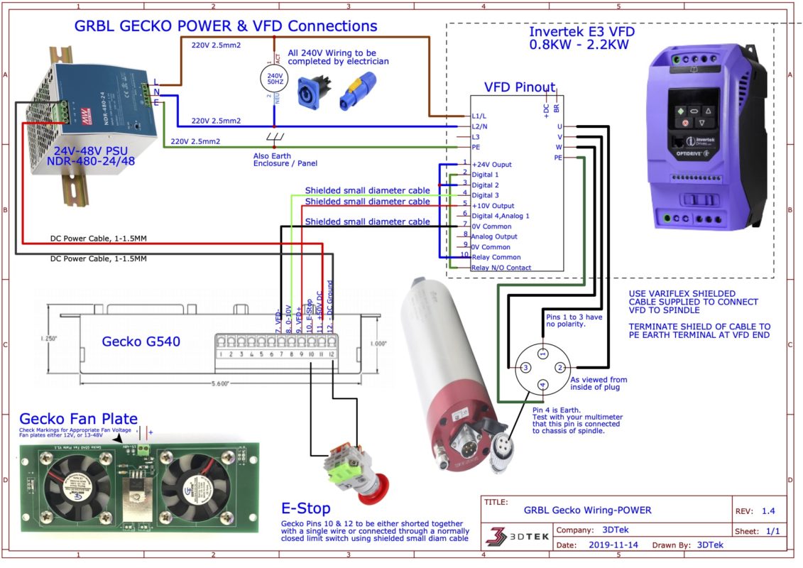
The first order of business is to upload grbl to the arduino. To clone the y axis. It has complete interfaces with cheap price and can connect external drive very suitable for diy or factory use. Please read important notes at bottom before powering up the vfd. Grbl is an extensive library and if you read through the documentation you can learn a lot many things. The wiring is simple but there is no indication if one of the switches is the schematic of the end sensor board which uses optocouplers.
Please contact 3dtek for any assistance wiring up or configuring these devices. Grbl gecko power vfd connections. Connect them according to the section. Grbl gecko stepper motor connections. Pin diagram for grbl v and v with the traditional layout.
Gallery of Grbl Wiring Diagram