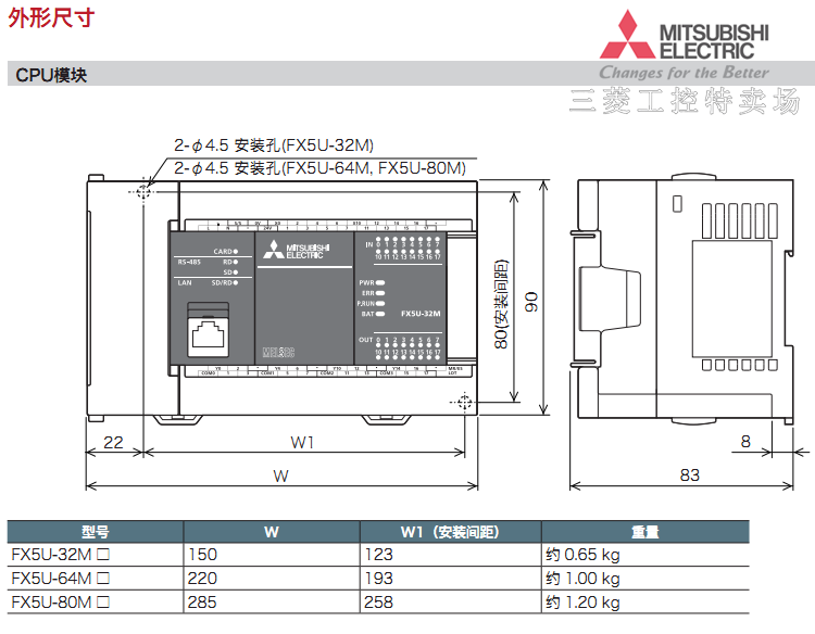
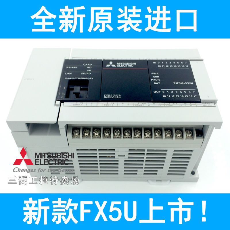
Mitsubishi electric fa site introduces melsec iq f series cad data information. The fx5u continues the fx tradition of total flexibility by offering a huge range of new and existing add on options which further enhance the built in functions of ethernet analogue io data logging position control security communications and networking.

레오콤 한국 블로그 Www Leocom Kr 2015 11 글 목록 2 Page
Fx5u 64mt ess wiring diagram. Failure to do so may cause fire equipment failures or malfunctions. 32 64 80 product 1 module. 1 overview 13 system configuration 9 1 13 system configuration system configurations to use the module fbs for this reference is shown below. Connect the power supply wiring to the dedicated terminals described in this manual. Analog input module fb for specifications of the module used refer to the melsec iq f fx5 users manualanalog control intelligent function. However when the installation work is completed make sure to remove the sheet to provide adequate ventilation.
The first model in the iq f series is the fx5u offering high performance in a compact cost effective package. Page 37 fx5u 64m ac power supply type ss 0v 16 x20 fx5u 64mres fx5u 64mtes com5 com0 com1 com2 com3 com4 fx5u 64mtess fx5u 80m ac power supply type ss 0v x40 42 fx5u 80mres fx5u 80mtes com0 3 com1 com2 com3 com4 com5 com6 fx5u 80mtess 2 specifications 210 terminal layout. Doing so may cause damage to the product. Melsec iq f fx5u users manual hardware. Refer to melsec iq f fx5u users manual hardware. Fx5u users manual hardware 1 safety precautions.
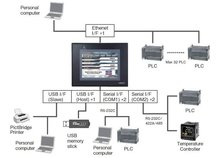
Fx5u cpu modules. Fx5u 32mrds fx5u 32mtdss fx5u 32mres fx5u 32mtess fx5u 64mrds fx5u 64mtdss fx5u 64mres fx5u 64mtess fx5u 80mrds fx5u 80mtdss fx5u 80mres fx5u. Failure to do so may cause electric shock or damage to the product. Do not wire vacant terminals externally. If an ac power supply is connected to a dc inputoutput terminal or dc power supply terminal the plc will burn out. Diagram 1 cmt series cmt3151 emt series emt3070 emt3105 emt3120 emt3150 mt ie mt8070ie mt6070ie mt8100ie mt8121ie mt8150ie mt xe mt8121xe mt8150xe hmi rs plc com1 fx5u rs422 485 4w terminal 9p male rx 1 sdb rx 2 sda tx 3 rdb tx 4 rda gnd 5 sg diagram 2.
Make sure to attach the terminal cover provided as an accessory before turning on the power or initiating operation after installation or wiring work. Make sure to cut off all phases of the power supply externally before attempting installation or wiring work. With cover open 1 products that do not have the genuine product certification label or nameplate are not covered by the warranty. Included items cpu module fx5u mres fx5u mtes fx5u mtess fx5u mrds fx5u mtds fx5u mtdss. Slits before the installation and wiring work to prevent foreign objects such as cutting and wiring debris.


