Wiring diagram 3 way switch with light at the end in this diagram the electrical source is at the first switch and the light is located at the end of the circuit. Pick the diagram that is most like the scenario you are in and see if you can wire your switch.
Crl 3 Way Switch Issues Telecaster Guitar Forum
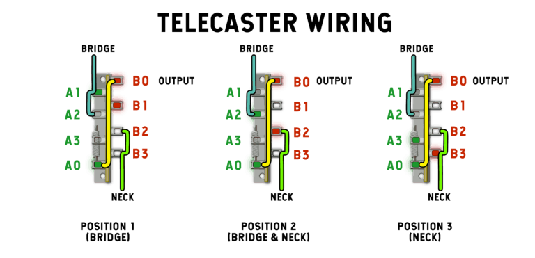
Crl 3 way switch wiring diagram. Im trying to understand how a new crl 3 way switch works what is connected to what when the switch is in the 3 different positions. The black and red wires between sw1 and sw2 are connected to the traveler terminals. Crl 3 way lever switch about this item crl pickup selector switches are famous for durable noise free reliability and easy wiring since the early days of electric instruments. Extra black wire is included for running a string ground to the bridge. Included in two stewmac wiring kits this 3 way crl lever switch is included in both of our tele wiring kits. Crl 3 way guitar pickup selector leverblade style switch.
When i cut out i left a touch of wire to match up but this doesnt help now. 3 way switch wiring diagram. Dont forget the wire solder shielding. These wiring kits contain black and non shielded wire plus shielded coaxial cable. I dont know how to interpret these diagrams. With these diagrams below it will take the guess work out of wiring.
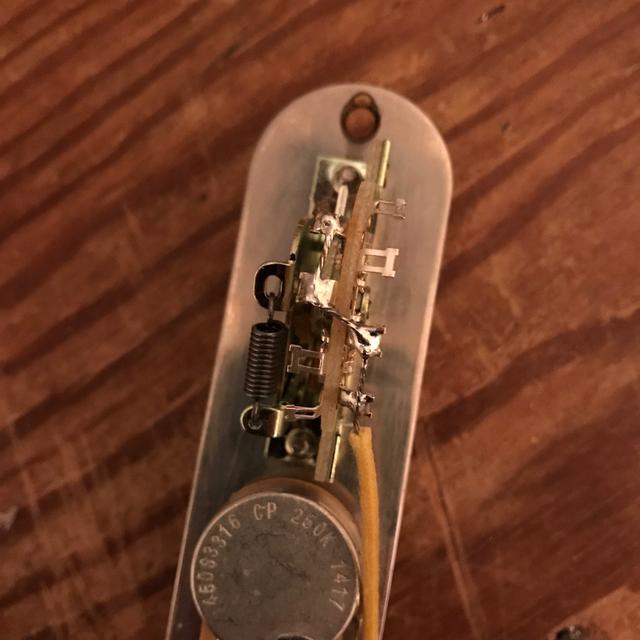
Basic guitar wiring diagram with 2 humbuckers 3 way lever switch two volumes and one tone control. Fits telecasters and most other guitars with 3 way leverblade style pickup selectors. With no instructions i started searching the original that broke was a flat type with all solder tabs to one side. Ready to get started. Take a closer look at a 3 way switch wiring diagram. The 3 way switch broke i went to the local music store and bought a crl 3 way.
Upgrade or replace your import switch with the best 3 way switch available. Rg wiring dimarzio neck bridge humbuckersarea middle single coil ibz 5 way switch 1 volume 1 push pull tone split all in positions 23 4. Heavy duty construction and superior dual contact design provides a long service live with noise free operation. Three wire cable runs between the switches and 2 wire cable runs to the light. I found some diagrams that show the lugs labeled a0 a1 a2 a3 b0 b1 b2 b3 and in colors red and blue in addition to some uncolored. Neck neck middle middle bridge middle bridge.
This might seem intimidating but it does not have to be. Click diagram image to openview full size version.
Gallery of Crl 3 Way Switch Wiring Diagram