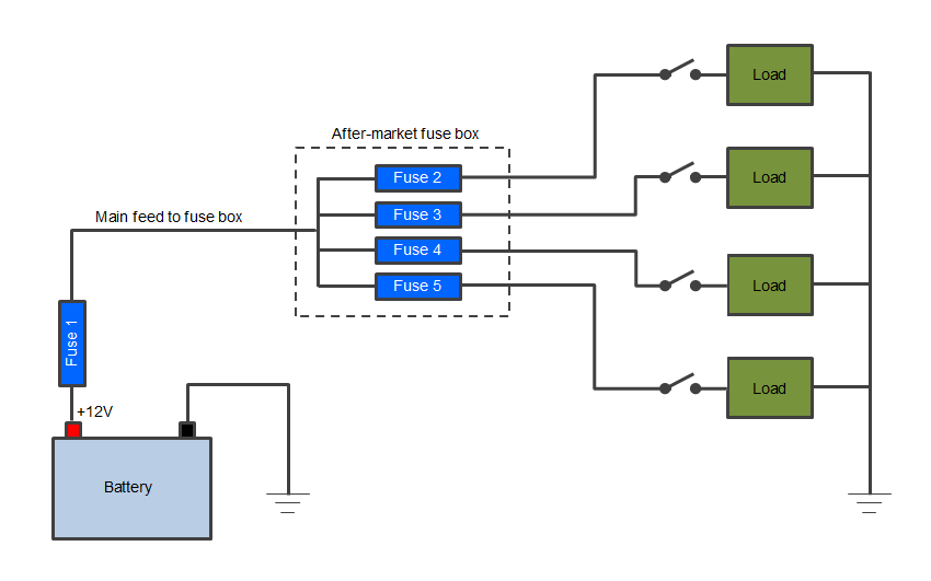
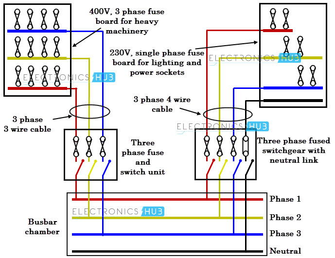
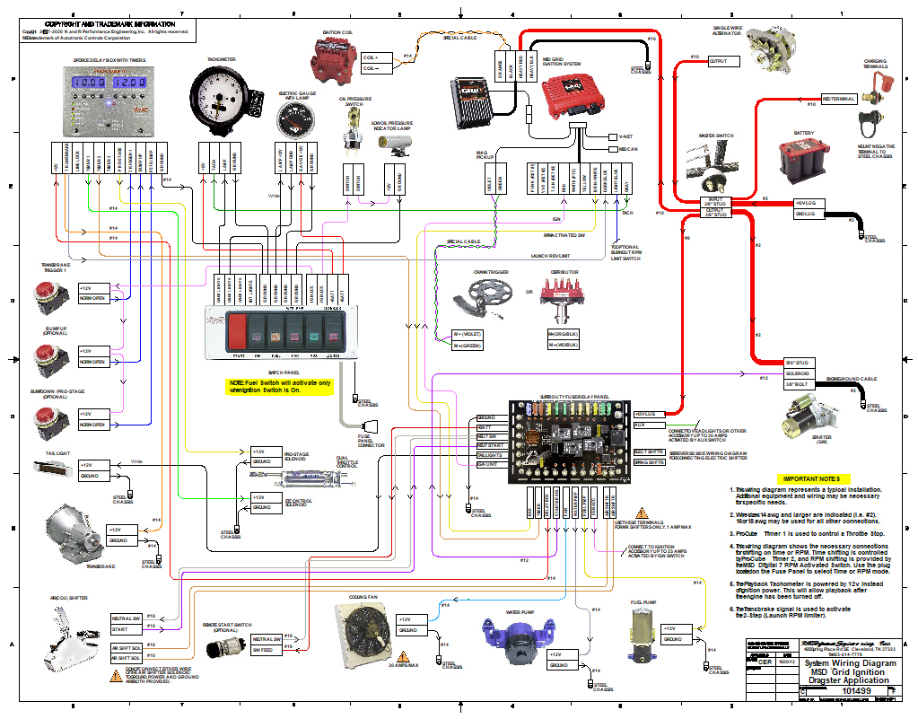
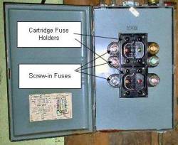
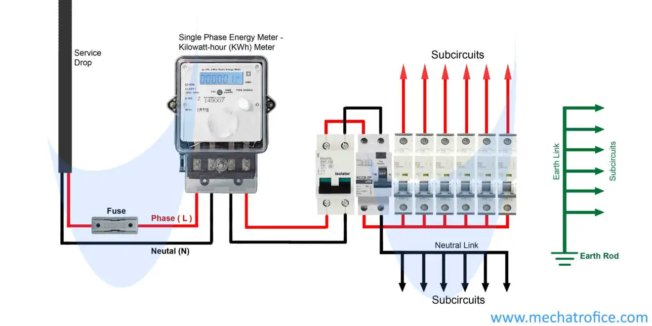
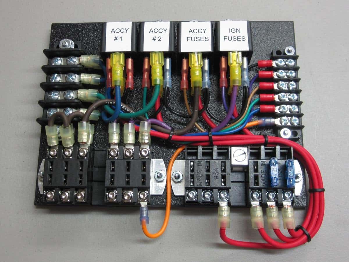
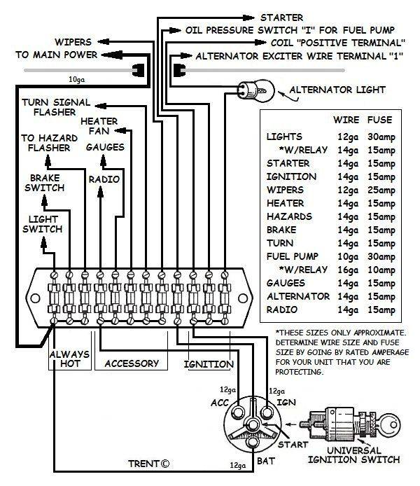
Electronic fuse circuit diagram. A wiring diagram is a simple visual representation of the physical connections and physical layout of an electrical system or circuit.

Rcd Fuse Box Wiring Diagram
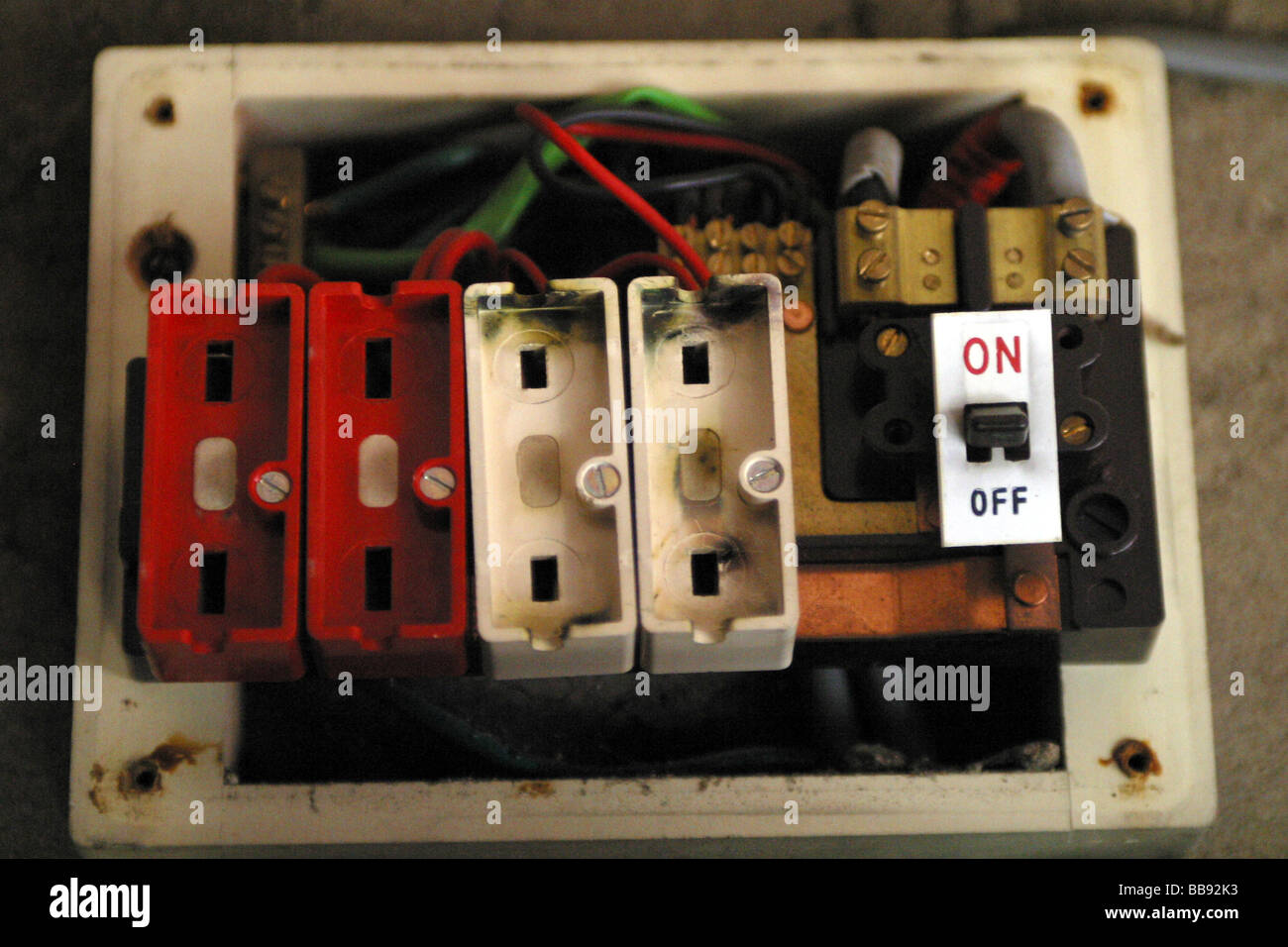
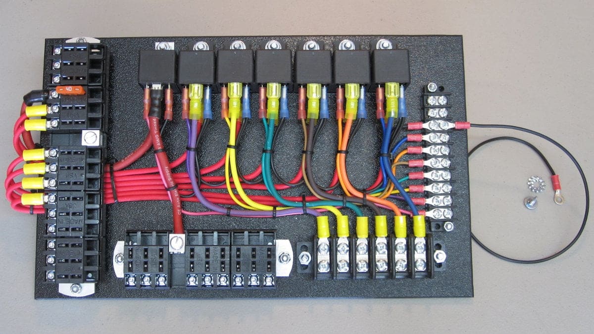
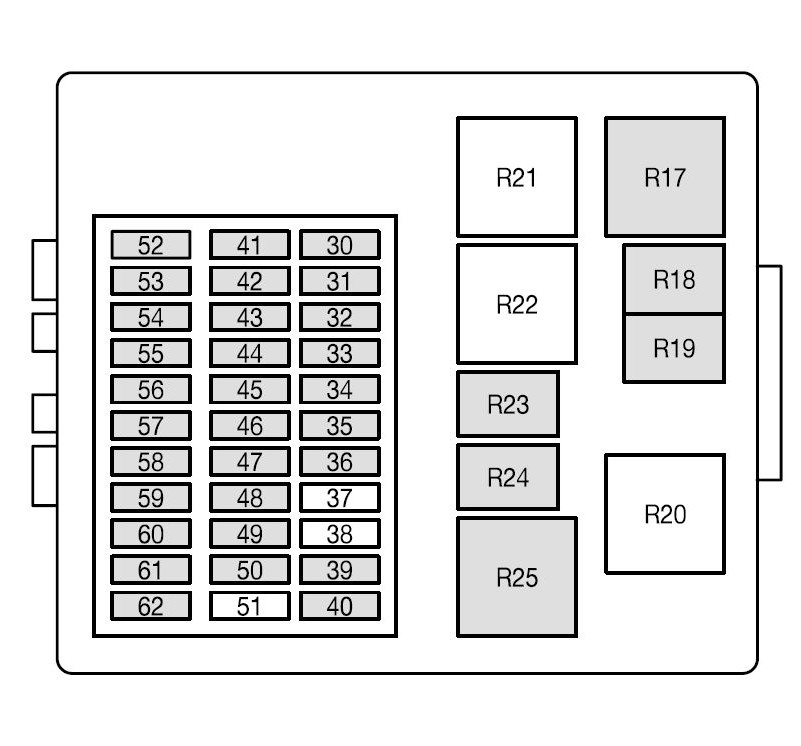
Fuse board wiring diagram. It shows the components of the circuit as simplified shapes and the capability and signal associates in the midst of the devices. Transistor t1 and resistor r1 form a 6 ma current source that together with zener diode d1 provides a constant voltage of 56 v with respect to the ve supply line. Here is a picture gallery about fuse box diagram 2005 ford f150 complete with the description of the image please find the image you need. 2005 f150 ford fuse panel diagram use your dvom and see if you within fuse box diagram 2005 ford f150 image size 544 x 496 px and to view image details please click the image. It shows how the electrical wires are interconnected and can also show where fixtures and components may be connected to the system. Boat fuse block wiring diagram wiring diagram is a simplified good enough pictorial representation of an electrical circuit.
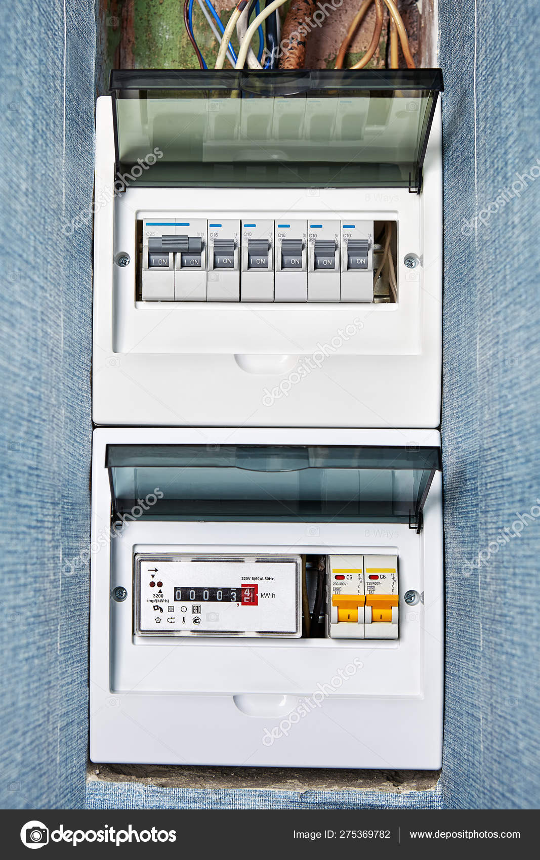
We have actually accumulated lots of images ideally this picture works for you and also aid you in finding the solution you are trying to find. Cj7 fuse box diagram thanks for visiting my web site this message will discuss regarding cj7 fuse box diagram. The size of the fuse and circuit breaker are similar to use but circuit breaker is more safe to use as compared to fuses due to automatic operation as you can reset it again if it trips ever. This gives the gate of t3 a sufficiently high negative voltage to keep this p channel mosfet conducting and thus providing the link between power. Electrical wiring diagram of a 230v single phase 63a distribution board consumer unit with rcd for ac units lighting 13a radial circuits.

