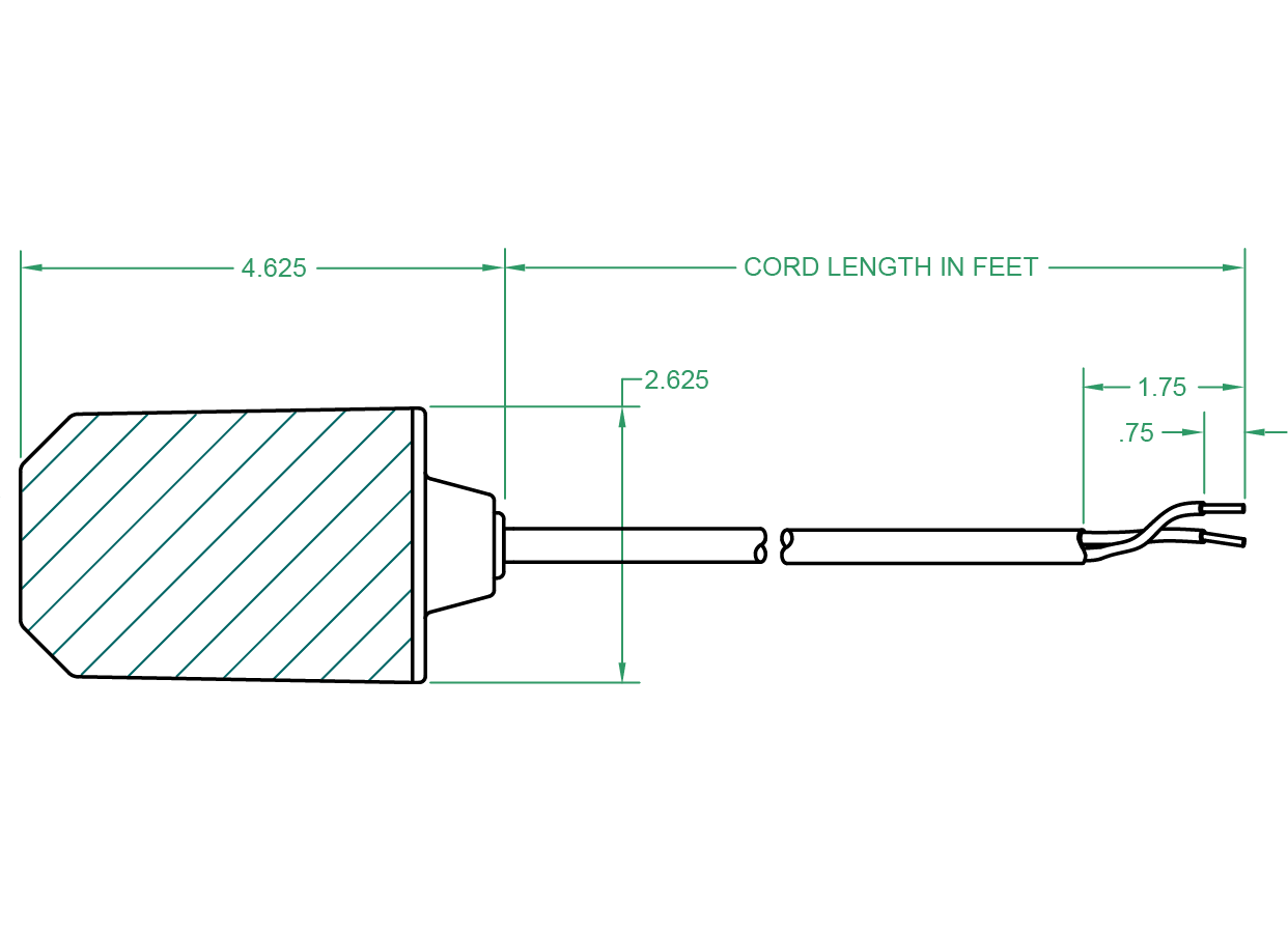
When the liquid level reaches the regulator the bulb tilts activating the internal micro switch which starts or stops a pump or triggers an alarm device. It shows the components of the circuit as simplified shapes and the capacity and signal links amid the devices.

27 Septic Tank Electrical Wiring Diagram Wiring Diagram List
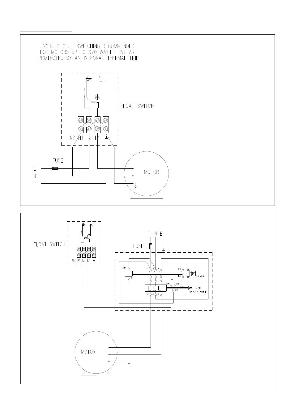
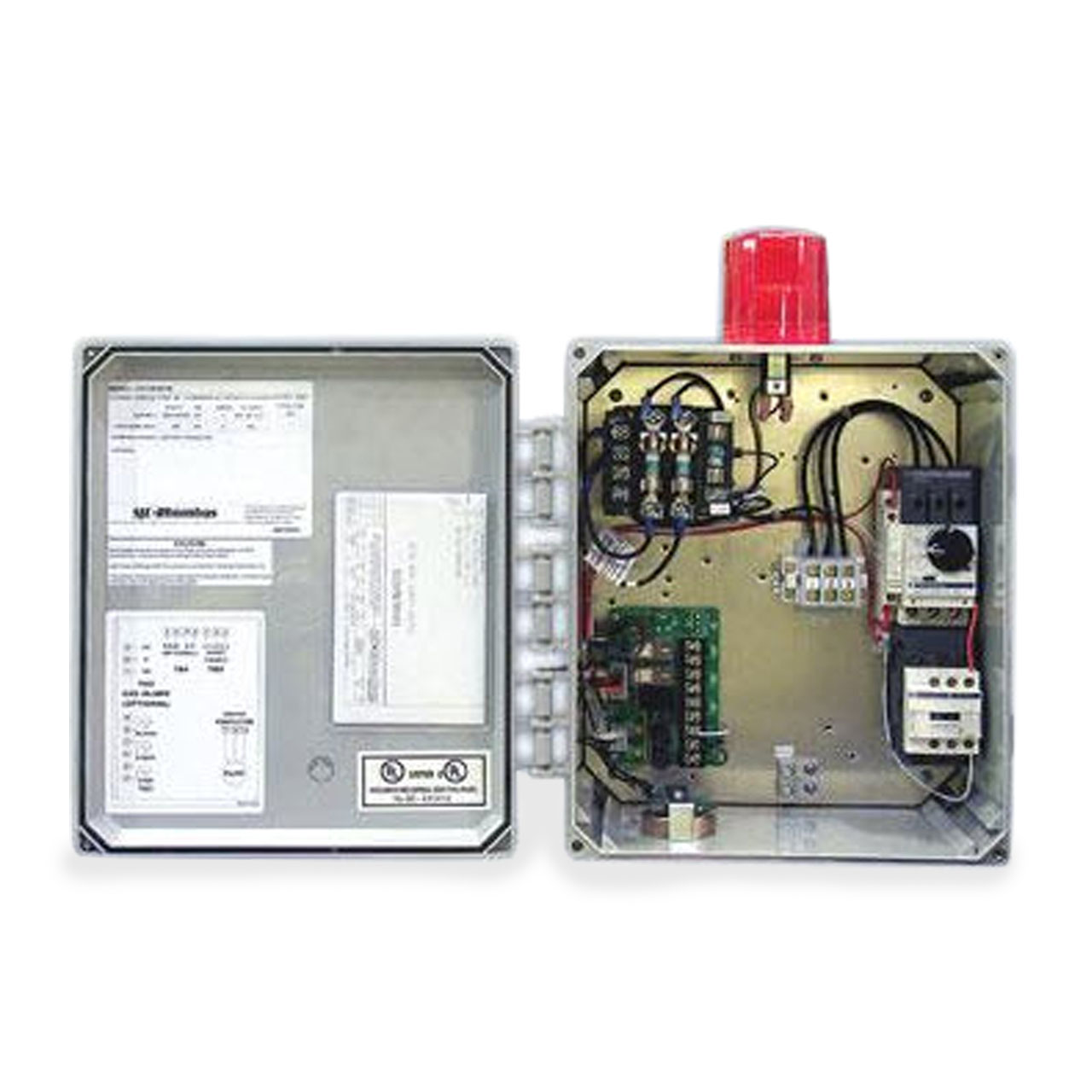
Flygt float switch wiring diagram. A two wire single pole single throw float switchthe rising action of the float can either close ie turn on a normally open circuit or it can open turn off a normally closed circuitinstallation scenarios might include a normally open float switch turning on a pump to empty a tank control schematic 2 or a normally closed. Posted on march 3 2018 august 9 2018 by headcontrolsystem. The minicas shall monitor both the series connected thermal switches and leakage sensors by outputting 12 vdc on a single two wire circuit. Flygt minicas wiring diagram wiring diagram is a simplified suitable pictorial representation of an electrical circuit. This is perfectly normal and the correct way to do it. Lets start with the most basic float switch.
Collection of float level switch wiring diagram. Flygt float switch wiring diagram free download at septic. However with a float body of polypropylene a cable of pvc or nbrpvc nitrilepvc rubber and a bending relief of epdm rubber the enm 10 is virtually insensitive to many aggressive liquids. In this video how to use float switch wiring single phase on off motor using float switch diagram installation for water tank. The flygt enm 10 level regulators are the ideal choice for most level control applications such as wastewater pumping stations and ground water or drainage pumping. The other leg will connect to the hot wire from the pump.
Most float switches have a white and black wire which means you will most likely have a white to black connection. One leg of the float switch will connect to the hot wire from the panel. Hello friends in this video i will tell you how to make the. Float switch wiring diagram wiring diagram is a simplified normal pictorial representation of an electrical circuit. Switches embedded in the stator end coils the flygt fls float switch type water in stator housing sensor and the flygt cls capacitive type water in oil sensor. A wiring diagram is a streamlined conventional pictorial.
Variety of septic tank float switch wiring diagram. It shows the components of the circuit as simplified shapes and the capability and signal friends amid the devices. It reveals the parts of the circuit as simplified forms as well as the power and signal links in between the tools. The table shows how resistant the enm 10 equipped with either pvc or nbrpvc nitrilepvc rubber cable is to different chemicals at two different temperatures. A wiring diagram is a simplified standard photographic representation of an electric circuit. Septic tank float switch wiring diagram collection.
Gallery of Flygt Float Switch Wiring Diagram