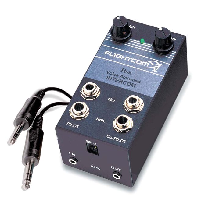
Flightcom portable ptt switch part number 103 0604 10 is designed specifically for the 403 and 403d intercoms. Do not attempt to combine both input and output functions on a single 35mm jack.

A D D E N D U M Manualzz
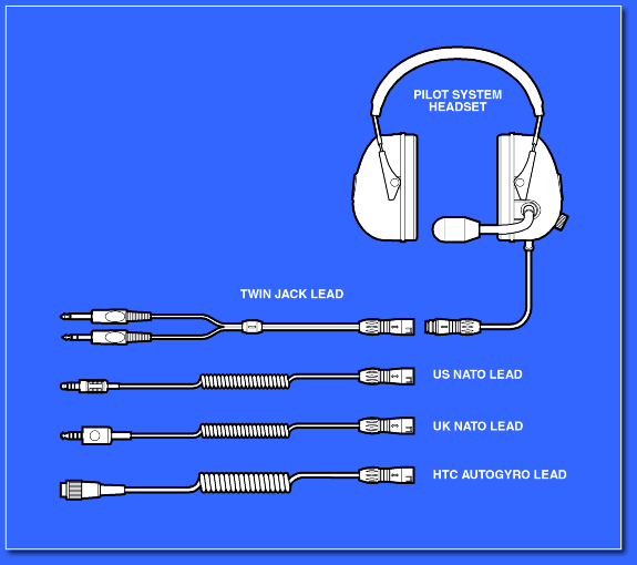
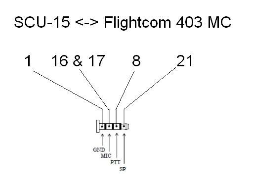
Flightcom 403 wiring diagram. Dip switches case top removal to open the model 403 or 403d intercom case. Read the manual thoroughly before using the intercom and consult with your ap mechanic or certified repair station prior to installation. Figure 5 jack mounting diagram stereomono. Flightcom 403 sq vol stereo optional ptt switches for 1 3 places flightcom 403 headset jacks for 2 6 places optional stereo or mono ics squelch volume isolate 403 intercom optional. Flightcom 403 sq vol stereo optional dcr control panel optional ptt switches for 1 3 places flightcom 403 headset jacks for 2 6 places optional stereo or mono ics squelch volume isolate 403. Circuit breaker ptt 7 pilot mic 7 2 13 9 hdph ptt 6 co pilot hdph mic mic 13 hdph hdph mic mic 13 hdph hdph mic 11.
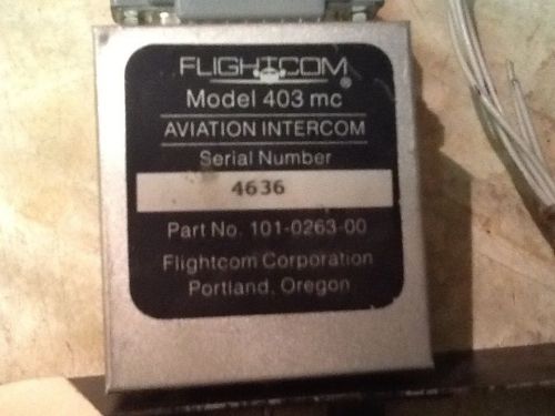
Wiring diagram is for auxiliary input allowing you to listen to a tape player or other source. To record from the intercom system auxiliary output install a second 35mm jack and connect it via one 1 47k resistor to the pilot s headphone output pin 9. Remove the two hex screws at the rear of the intercom on either side of the 25 pin d sub connector do not remove the screw on the side of the case. Wiring harness installation instructions this wiring harness is intended for use with 2 to 4 place intercom installations including the flightcom 403 403mc and 403lsa. 1 wiring harness for dcr with button switch and led. Flightcom 403 wiring diagram.
Flightcom mc download as pdf file pdf text file txt or read online. Connect the jacks with the proper wire and according to the wiring diagram on. Figure 5 jack mounting diagram stereomono 3. It r ptt 7 t mic 7 2 13 9 h ptt 6 t h mic mic. However im now to the point of wiring in my radio and intercom.
Gallery of Flightcom 403 Wiring Diagram